Weider Weevbe1926 Instruction Manual - Page 8
Warning
 |
View all Weider Weevbe1926 manuals
Add to My Manuals
Save this manual to your list of manuals |
Page 8 highlights
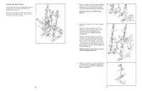
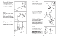
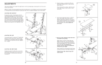
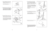
5. Orient the Frame (8) so that the hexagonal 5 holes are on the bottom. Next, apply a small amount of the included grease to an M10 x 72mm Bolt (64). Attach the Frame to the Crossbar (5) with the Bolt and an M10 Nylon Locknut (58). Do not overtighten the Nylon Locknut; the Frame must pivot easily. Fully tighten a Curl Post Knob (56) into the Crossbar (5) and the Frame (8). 56 5 8 58 64 Grease Hole 6. Tighten the "T"-handle (45) into the Seat Carriage (42). Pull the "T"-handle (45) out as far as it will go and slide the Seat Carriage (42) onto the Frame (8). Attach the Front Leg (12) to the Frame (8) with two M8 x 52mm Bolts (59), two M8 x 58mm Bolts (46), six M8 Washers (50), and four M8 Nylon Locknuts (49). Do not tighten the Nylon Locknuts yet. Hexagonal Holes 6 49 49 50 50 12 45 8 50 50 42 46 59 7. Set the pins on the Adjustment Tube (9) down 7 into a set of brackets on the Left and Right Upright Bases (3, 4). See steps 1-6. Tighten the M10 Nylon Locknuts (58) and the M8 Nylon Locknuts (49) used in these steps. 4 9 Pin Pin 3 8 ATTACHING THE CURL POST Remove the 45mm Square Inner Cap (34) from the Front Leg (12). Insert the Curl Post (13) into the Front Leg and align the holes in the Front Leg and the Curl Post. Secure the Curl Post with the Curl Knob (56). Fully tighten the Curl Post Knob. STORING THE CURL POST When performing exercises that do not require the Curl Pad (20), remove the Curl Post (13) from the Front Leg (12) and store it in the storage tube on the Right Stabilizer (2). Press the 45mm Square Inner Cap (not shown) into the Front Leg (not shown). 20 13 34 56 12 20 13 2 ADDING WEIGHT TO THE LEG LEVER To use the Leg Lever (18), slide the desired amount of weight (not included) onto the Weight Tube (19). Secure your weights with a Spring Clip (51). WARNING: Do not place more than 150 pounds (69 kg) on the Weight Tube (19). Secure your weights with Spring Clips (51). WEIGHT RESTS To use a barbell (not included) with the weight bench, first move the Weight Rests (39) to the correct height for the exercise to be performed. Engage the locking bars around the Uprights (28, 31). WARNING: Always place both Weight Rests (39) at the same height. Make sure the locking bars are securely wrapped around the Uprights (28, 31) before setting a barbell on them. 13 18 Weight 19 51 28 39 Locking Bar 31
-
 1
1 -
2
-
 3
3 -
 4
4 -
 5
5 -
 6
6 -
 7
7 -
 8
8 -
 9
9 -
 10
10
 |
 |
