Weider Weevbe1926 Instruction Manual - Page 9
Adjustments
 |
View all Weider Weevbe1926 manuals
Add to My Manuals
Save this manual to your list of manuals |
Page 9 highlights
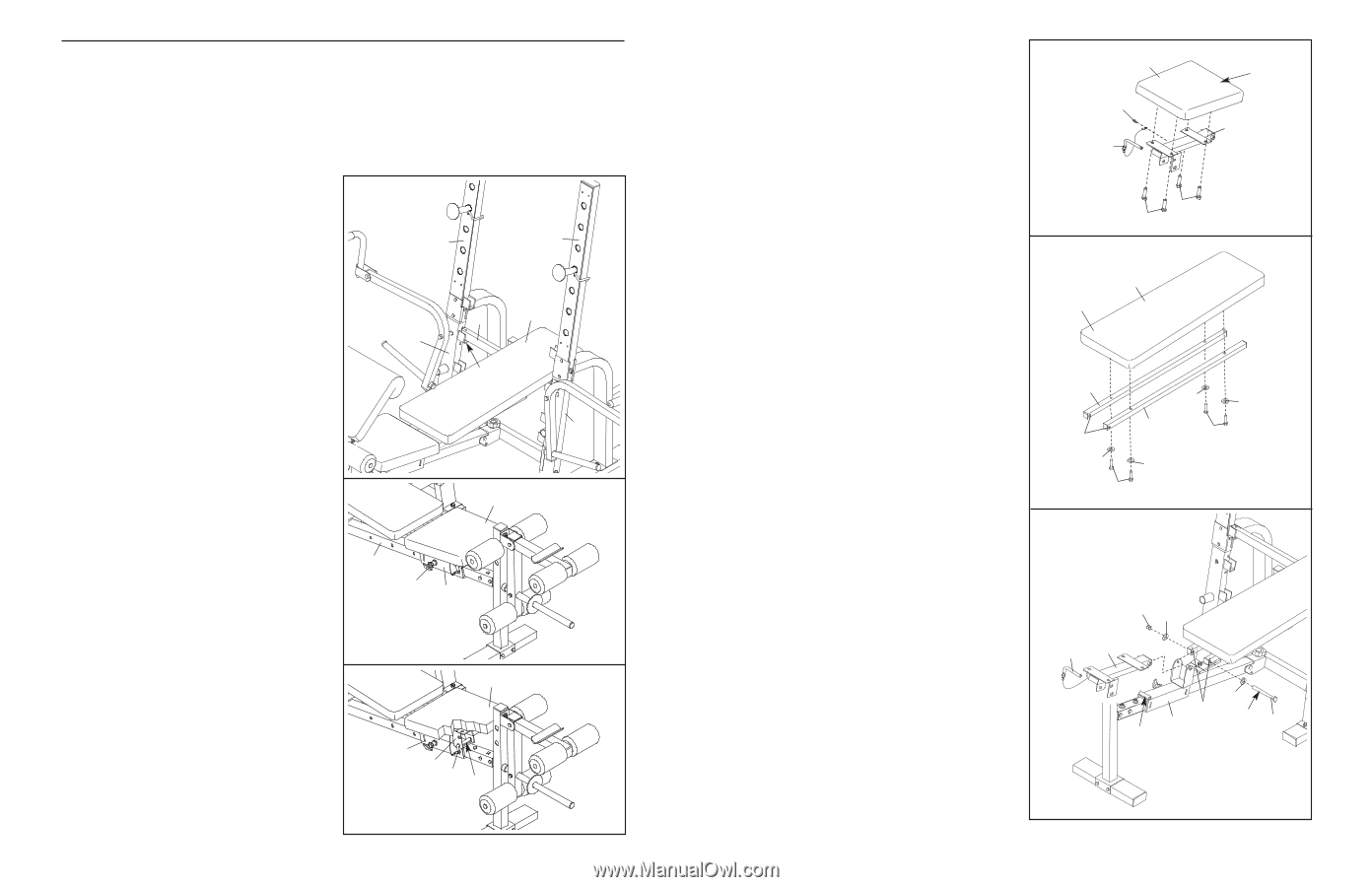
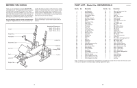
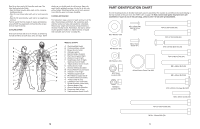
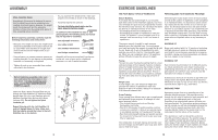
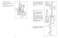
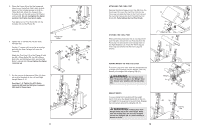
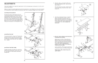
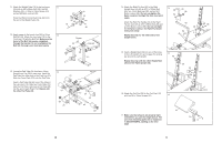
ADJUSTMENTS This section explains how to adjust the weight bench. See the accompanying exercise guide to see the correct form for each exercise. Make sure all parts are properly tightened each time the weight bench is used. Replace any worn parts immediately. The weight bench can be cleaned with a damp cloth and a mild, non-abrasive detergent. Do not use solvents. ADJUSTING THE BACKREST To adjust the position of the Backrest (22), first move the seat carriage to the desired position (see ADJUSTING THE SEAT below). Then, move the Adjustment Tube (9) to the desired height. Make sure the pins on the Adjustment Tube are inserted into a set of brackets on the Left and Right Upright Bases (3, 4) or the Left and Right Uprights (28, 31). Finally, rest the Backrest on the Adjustment Tube. 28 31 9 22 4 Pin 3 ADJUSTING THE SEAT To move the Seat (21), loosen the "T"-handle (45) and pull it out as far as it will go. Slide the Seat Carriage (42) to the desired location and engage the "T"-handle into the Frame (8). Then, retighten the "T"-handle. 21 8 45 42 ADJUSTING THE SEAT FRAME To adjust the angle of the Seat (21), remove the Seat Pin (40) and reinsert it into the other hole in the Seat Frame (10) and the tube on the Seat Carriage (42). 21 42 10 40 Tube 12 8. Attach the tether on the Seat Pin (40) to the 8 Seat Fame (10) with an M4 x 16mm Self-tap- ping Screw (57). Orient the Seat (21) as shown. Attach the Seat to the Seat Frame (10) with four M6 x 16mm Screws (41). 21 57 40 Wide End 10 9. Orient the two Backrest Frames (17) with the holes in the position shown and orient the Backrest (22) with the wide end in the position shown. Attach the Backrest to the two Backrest Frames with four M6 x 40mm Screws (48) and four M6 Washers (54). Do not tighten the Screws yet. 9 Wide End 41 41 22 10. Note: For clarity, the Seat (21 [see step 8]) is not shown in this drawing. Apply grease to an M10 x 145mm Bolt (53). Attach the Seat Frame (10) and the Backrest Frames (17) to the Seat Carriage (42) with the Bolt, two M10 Washers (43), and an M10 Nylon Locknut (58). Do not overtighten the Locknut; the Seat Frame and the Backrest Frames must pivot easily. Insert the Seat Pin (40) through the Seat Frame (10) and into the tube on the Seat Carriage (42). Tighten the four M6 x 40mm Screws (48) used in step 9. 17 Holes 54 54 17 48 54 54 48 10 58 43 40 10 43 42 17 Grease 53 Tube 9
-
 1
1 -
2
-
3
-
 4
4 -
 5
5 -
 6
6 -
 7
7 -
 8
8 -
 9
9 -
 10
10
 |
 |