Weslo 330i Treadmill Canadian English Manual - Page 7
Erly, The Console May Be Damaged When
 |
View all Weslo 330i Treadmill manuals
Add to My Manuals
Save this manual to your list of manuals |
Page 7 highlights
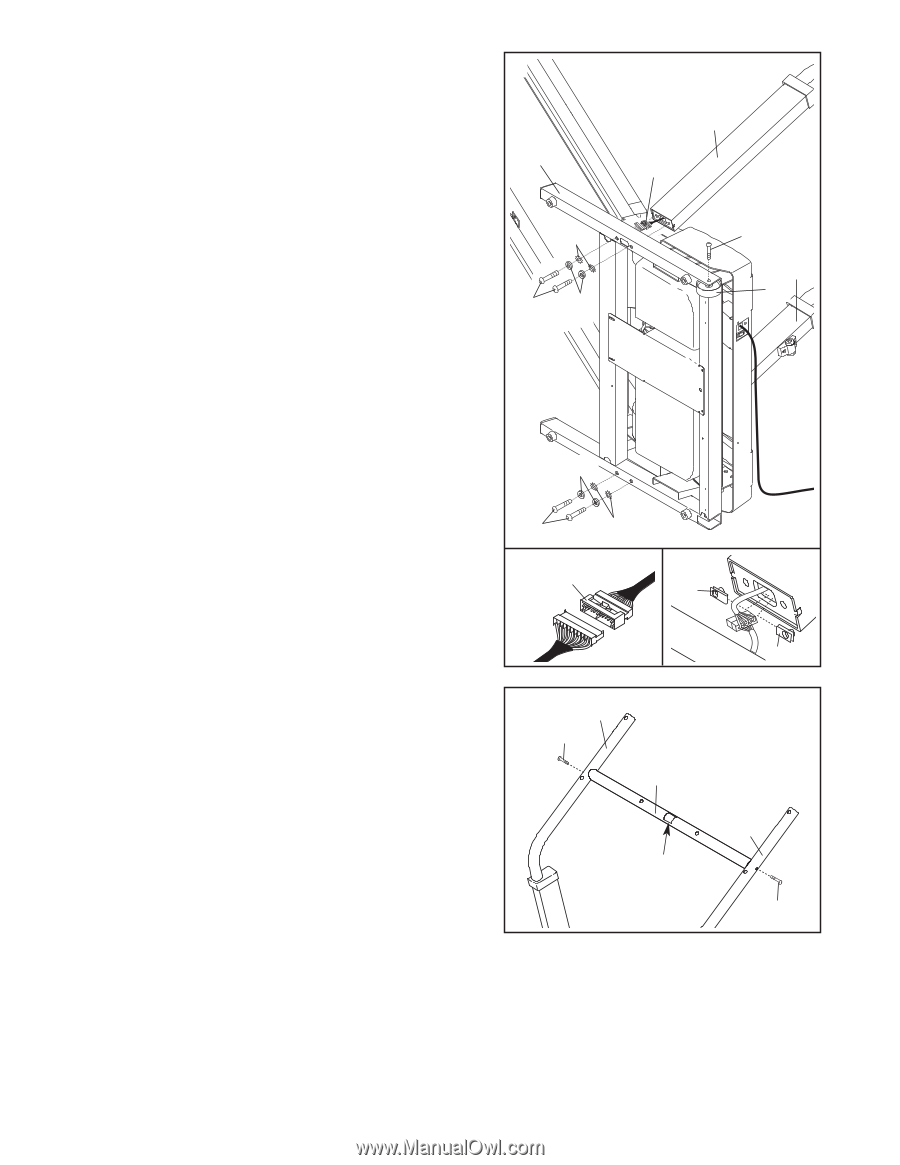
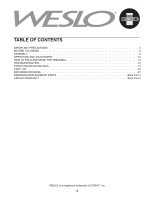
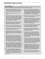
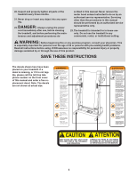
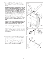
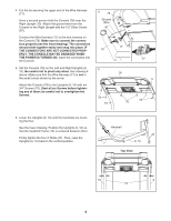
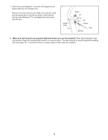
2. Identify the Right Upright (10), which has the Wire Harness (17) inside of it. Orient the Right Upright as shown. Cut the band securing the lower end of the Wire Harness. Have a second person hold the Right Upright (10) near the Base (82). Connect the Wire Harness (17) to the wire harness extending from the Base. Make sure to connect the connectors properly (see drawing 2a). The connectors should slide together easily and snap into place. IF THE CONNECTORS ARE NOT CONNECTED PROPERLY, THE CONSOLE MAY BE DAMAGED WHEN THE POWER IS TURNED ON. See drawing 2b. Make sure that there are two U-Nuts (101) in the lower end of the Right Upright. Carefully wrap the wires around the connectors. Insert the connectors and the excess Wire Harness into the Base as shown, and then hold the Right Upright against the Base. Be careful not to pinch the wires. Insert two 3" Bolts (47), with two Washers (29) and two Star Washers (81), into the Base (82) and loosely thread the Bolts into the lower end of the Right Upright (10). Attach a Front Wheel (95) to the Base (82) with a Wheel Bolt (86). Do not overtighten the Bolt; the Wheel must be able to turn freely. With the help of a second person, tip the treadmill onto its right side. Attach the Left Upright (9) and the other Wheel (not shown) as described above. Note: There are no wires in the Left Upright. 2 82 81 47 29 10 17 86 9 95 29 47 81 2a 2b 17 101 3. With the help of a second person, tip the treadmill onto the Base (not shown), with the Left and Right Uprights (9, 10) in a vertical position. Open part bag B. Hold the Console Crossbar (88) between the handrails on the Left and Right Uprights (9, 10). Make sure that the square hole in the Crossbar is on top as shown. Attach the Crossbar with two Crossbar Bolts (56). Firmly tighten the Crossbar Bolts. 3 9 56 88 Square Hole 101 10 56 7
-
 1
1 -
 2
2 -
 3
3 -
 4
4 -
 5
5 -
 6
6 -
 7
7 -
 8
8 -
 9
9 -
 10
10 -
 11
11 -
 12
12 -
13
-
14
-
15
-
16
-
17
-
18
-
19
-
20
-
21
-
22
-
23
-
24
 |
 |