Weslo Aer0bic Glide Plus User Manual - Page 4
adjustable
 |
View all Weslo Aer0bic Glide Plus manuals
Add to My Manuals
Save this manual to your list of manuals |
Page 4 highlights
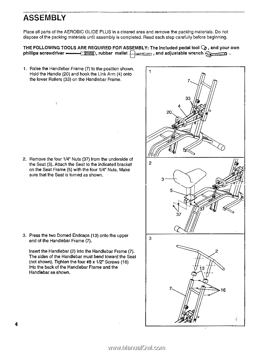
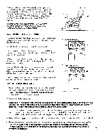
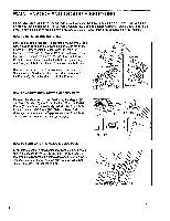
ASSEMBLY Place all parts of the AEROBIC GLIDE PLUS in a cleared area and remove the packing materials. Do not dispose of the packing materials until assembly is completed. Read each step carefully before beginning. THE FOLLOWING TOOLS ARE REQUIRED FOR ASSEMBLY: The Included pedal tool Q) , and your own phillips screwdriver rubber mallet , and adjustable wrench 'S;; ;;D 1. Raise the Handlebar Frame (7) to the position shown. Hold the Handle (20) and hook the Link Arm (4) onto 1 the lower Rollers (33) on the Handlebar Frame. 7 33 4 20 2. Remove the four 1/4" Nuts (37) from the underside of the Seat (3). Attach the Seat to the indicated bracket on the Seat Frame (5) with the four 1/4" Nuts. Make sure that the Seat is turned as shown. 2 3 5 37 3. Press the two Domed Endcaps (13) onto the upper end of the Handlebar Frame (7). 3 Insert the Handlebar (2) into the Handlebar Frame (7). The sides of the Handlebar must bend toward the Seat (not shown). Tighten the four #8 x 1/2" Screws (16) into the back of the Handlebar Frame and the Handlebar as shown. 7 37 2 13 16 4
-
 1
1 -
 2
2 -
 3
3 -
 4
4 -
 5
5 -
 6
6 -
 7
7 -
 8
8 -
 9
9 -
 10
10 -
11
-
12
 |
 |