Weslo Cadence 25 Treadmill User Manual - Page 9
Damaged When The Power Is Turned On.
 |
View all Weslo Cadence 25 Treadmill manuals
Add to My Manuals
Save this manual to your list of manuals |
Page 9 highlights
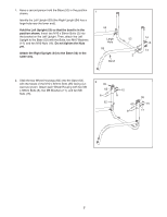
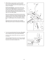
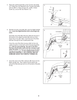
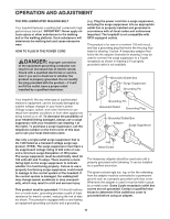
5. Place the Left Handrail (56) on the Console Assembly (91). Attach the Left Handrail to the Console Assembly 5 with two M4.2 x 19mm Screws (4), an M5 x 16mm 5 Screw (5), and an M5 Star Washer (12). 12 56 4 91 6. Hold the Console Assembly (91) near the Right Upright (54). Touch the Right Handrail (55) to discharge any static. Insert the end of the Wire Harness (98) into the hole in the bottom of the Right Handrail (55) and out of the large hole in the side. Next, insert the end of the Wire Harness through the two looped plastic ties. Press the end of the Wire Harness (98) into the indicated connector on the back of the Console Assembly (91). See the inset drawing. The end of the Wire Harness should slide easily into the connector and snap into place. If it does not, turn the end of the Wire Harness and try again. IF THE CONNECTOR IS NOT INSERTED PROPERLY, THE CONSOLE MAY BE DAMAGED WHEN THE POWER IS TURNED ON. 6 Connector 91 54 98 Plastic Ties 55 98 7. Insert the slack in the Wire Harness (98) down into the Right Upright (54). Then, tighten the two plastic ties 7 around the Wire Harness and cut off the ends of the plas- tic ties. 54 98 Plastic Ties 9
-
 1
1 -
2
-
3
-
 4
4 -
 5
5 -
 6
6 -
 7
7 -
 8
8 -
 9
9 -
 10
10 -
 11
11 -
 12
12 -
 13
13 -
 14
14 -
15
-
16
-
17
-
18
-
19
-
20
-
21
-
22
-
23
-
24
-
25
-
26
-
27
-
28
 |
 |
