Weslo Cadence 255 Dr Treadmill English Manual - Page 6
Set the Console Base 87 on the Handrails 4. Thread
 |
View all Weslo Cadence 255 Dr Treadmill manuals
Add to My Manuals
Save this manual to your list of manuals |
Page 6 highlights
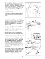
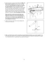
3. If there are plastic ties in the brackets on the Handrails (4), remove the plastic ties. Hold one of the Handrails near the right Upright (38) as shown. Insert the Wire Harness (53) up through the bracket on the Handrail and out of the round hole in the side of the Handrail. If necessary, use needlenose pliers to pull the Wire Harness out of the hole. Be careful not to damage the Wire Harness. Insert the brackets on the Handrails (4) into the upper ends of the Uprights (38). Finger tighten four 1" Bolts (16) with Handrail Washers (40) into the Uprights (38) and the Handrails (4) as shown. 3 4 Connectors 4 16 53 40 Bracket 40 16 38 16 40 16 38 4. Set the Console Base (87) on the Handrails (4). Thread four 3/4" Screws (5) into the Handrails and the Console Base. After you have started all four Screws, tighten the Screws until they are snug; do not overtighten the Screws. Note: It may be helpful to press down on the top of the Console Base above the Handrails as you tighten the Screws. See step 3. Firmly tighten, but do not overtighten, the four 1" Bolts (16). Insert the Wire Harness (53) through the two indicated plastic ties on the Console Base (87) and up through the hole in the Console Base as shown. 5. Hold the Console (11) near the Console Base (87). Touch the right Handrail (4) to discharge any static. Next, insert the Wire Harness (53) through the plastic tie labeled C in the drawing at the right. Locate the two connectors on the Wire Harness (53). Plug the wider connector into the connector labeled A in the drawing at the right (see drawing 5b). The connectors should slide together easily and snap into place. If they do not, turn the connector on the Wire Harness and try again. Insert the other connector through the plastic tie labeled D; plug the connector into the connector labeled B (see drawing 5c). IF THE CONNECTORS ARE NOT INSERTED PROPERLY, THE CONSOLE MAY BE DAMAGED WHEN THE POWER IS TURNED ON. See drawing 5a. Pull any slack in the Wire Harness (53) through the two ties. Make sure that the end of the Wire Harness indicated by the arrow is routed as shown. Securely tighten the plastic ties around the Wire Harness. Cut off the end of each plastic tie. 4 53 4 87 4 Plastic Ties 5 5 5 11 87 4 Tie C 53 A Tie D B 5a Tie Tie 53 5b 5c A 53 B 53 6
-
 1
1 -
 2
2 -
 3
3 -
 4
4 -
 5
5 -
 6
6 -
 7
7 -
 8
8 -
 9
9 -
 10
10 -
 11
11 -
 12
12 -
13
-
14
-
15
-
16
-
17
-
18
-
19
 |
 |
