Weslo Cadence 400cs English Manual - Page 6
Extension Leg 34 with a Handrail Bolt 91, a Handrail - parts
 |
View all Weslo Cadence 400cs manuals
Add to My Manuals
Save this manual to your list of manuals |
Page 6 highlights
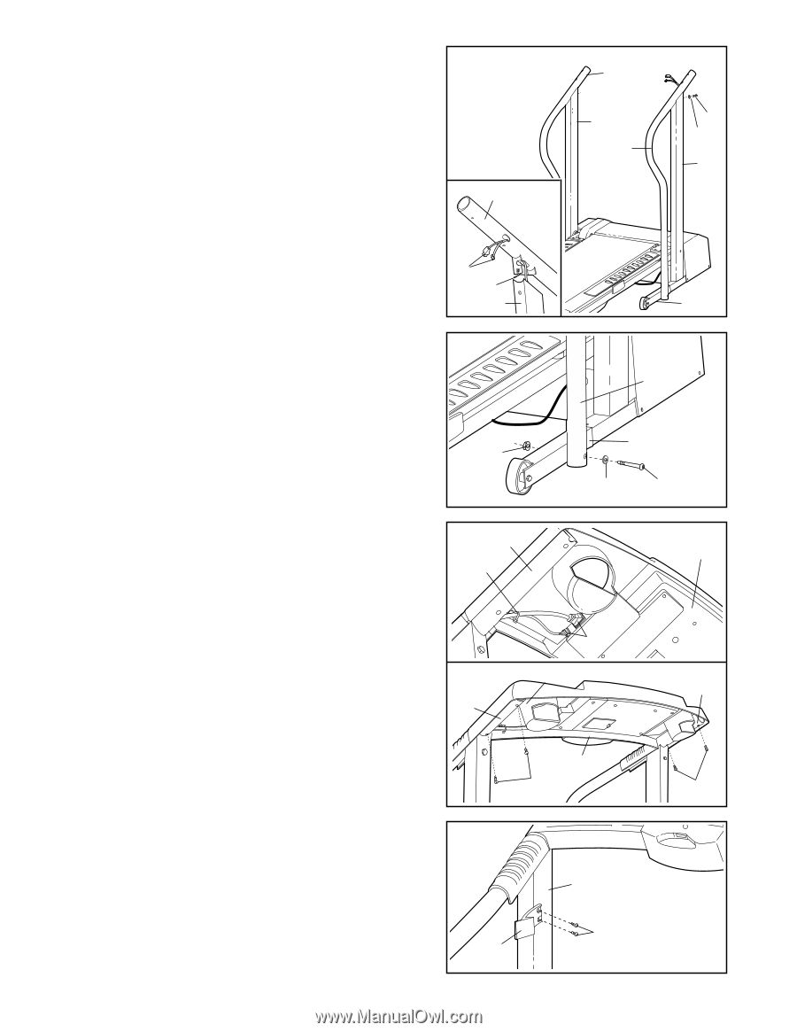
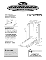
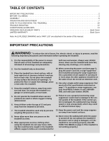
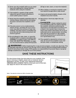
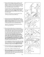
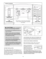
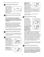
3. Refer to the inset drawing. If there is a plastic tie in the Cage Nut (70) in the Right Handrail (88), remove the plastic tie. Pull about 6" of the Wires (21) out of the Right Upright (11). Route the Wires up through the bracket on the Right Handrail and out of the indicated hole. If necessary, use needlenose pliers to pull the Wires. Insert the bracket on the Right Handrail (88) into the right Upright (11), with the lower end of the Right Handrail beside the Extension Leg (34). Tighten a Short Handrail Bolt (89) with a Small Handrail Washer (39) into the upper end of the Upright. Attach the Left Handrail (1) as described above. Note: There are no wires in the left Upright (11). 4. Attach the lower end of the Right Handrail (88) to the Extension Leg (34) with a Handrail Bolt (91), a Handrail Washer (92), and a Handrail Nut (93) as shown. Do not tighten the Handrail Nut yet. Note: It may be necessary to push on the lower end of the Handrail to align the hole in the Handrail with the hole in the Extension Leg. Attach the Left Handrail to the left Extension Leg (not shown) as described above. 5. Place the Console Base (46) on the Handrails (88, 1) (only the Right Handrail is shown). Pull out just enough of the two Wires (21) to connect them to the two connectors in the Console Base. Make a loop with the indicated plastic tie and insert the end through the tie holder on the bottom of the Console Base. Plug the Wire that has a red connector into the corresponding connector in the Console Base. If the connectors do not fit together easily, rotate them and then plug them in. Next, plug the other Wire into the other connector in the Console Base. Important: Make sure that both Wires are fully inserted. WARNING: Do not disconnect or connect the Wires while the treadmill power cord is plugged in. Pull the plastic tie tight and cut off the end. Refer to drawing 5b. Thread four Screws (96) into the Right and Left Handrails (88, 1) and the Console Base (46). After all four Screws have been started, tighten the Screws until they are snug; do not overtighten the Screws. 6. Attach the Storage Latch (14) to the left Upright (11) with two Screws (96). Do not to overtighten the Screws. Refer to step 4. Tighten the Handrail Nuts (93). 7. Make sure that all parts are properly tightened before you use the treadmill. Keep the included allen wrench in a secure place. (The allen wrench is used to adjust the walking belt [see page 13]). To protect the floor or carpet, place a mat under the treadmill. 6 3 88 21 70 11 4 93 5a 88 Tie 1 11 88 89 39 11 34 88 34 92 91 46 21 5b 21 1 88 46 96 96 6 11 96 14
-
 1
1 -
 2
2 -
 3
3 -
 4
4 -
 5
5 -
 6
6 -
 7
7 -
 8
8 -
 9
9 -
 10
10 -
 11
11 -
 12
12 -
13
-
14
-
15
-
16
-
17
-
18
-
19
 |
 |