Weslo Cadence 70 Instruction Manual - Page 8
How To Fold And Move The Treadmill
 |
View all Weslo Cadence 70 manuals
Add to My Manuals
Save this manual to your list of manuals |
Page 8 highlights
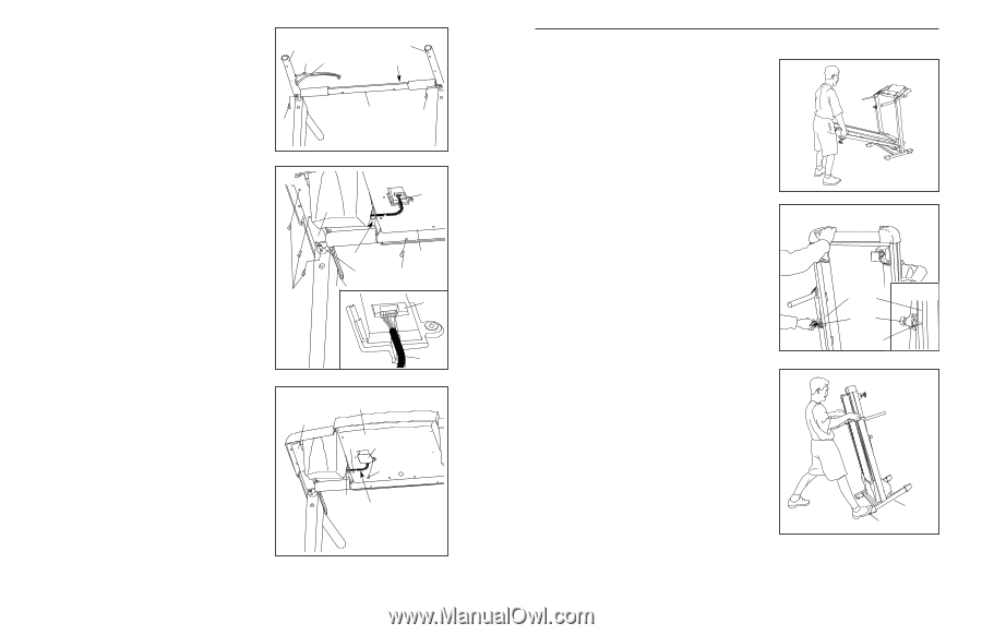
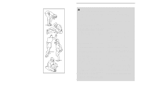
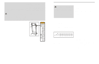
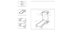
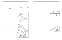
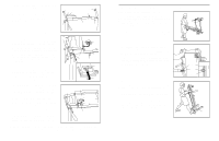
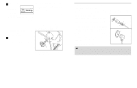
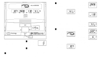
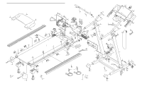
6. Attach the end of the ground wire to the small hole in the side of the Right Handrail (41) with a Silver Ground Screw (66). Open part bag C. Attach the Crossbar (39) to the Right Handrail (41) and the Left Handrail (40) with two Crossbar Screws (37). Do not tighten the Crossbar Screws yet. Make sure that the rectangular hole in the Crossbar is on the indicated side. 6 41 Ground 66 Wire 40 Hole 39 37 37 7. Place the Console Base (67) on the Right Handrail (41) and the Left Handrail (not shown). Insert the Wire Harness (65) through the indicated nylon tie on the Console Base (67). Next, touch the Right Handrail (41) to discharge any static. See drawing 7a. Find the connector on the end of the Wire Harness. Insert the connector into the red socket beneath the Console (69). The connector should slide easily into the socket and snap into place. If the connector does not slide easily and snap into place, turn the connector and then insert it. IF THE CONNECTOR IS NOT INSERTED PROPERLY, THE CONSOLE MAY BE DAMAGED WHEN THE POWER IS TURNED ON. Identify the 3/4" Screws (38); be careful not to confuse the 3/4" Screws with the 1/2" Screw (5). Attach the Console Base (67) to the Right Handrail (41) and the Left Handrail (not shown) with eight 3/4" Screws (only four Screws are shown). Start all eight Screws before tightening them. Do not overtighten the Screws. Tighten the Crossbar Screws (37). 8. Press the Wire Harness (65) into the recessed track on the back of the Console Base (67). Note: There may be a cylinder on the Wire Harness preventing it from being inserted into the track. Press as much Wire as possible into the track. Insert the excess Wire Harness (65) into the large hole in the side of the Right Handrail (41). Securely tighten the nylon tie to prevent the Wire Harness from slipping. Then, cut off the end of the nylon tie. Attach the Access Door (84) to the Console Base (67) with the 1/2" Screw (5). Tighten, but do not overtighten, the bolts used in step 5. With the help of a second person, lower the uprights and firmly tighten the bolts used in steps 2. 7 65 41 Tie 37 67 38 38 7a 69 65 8 41 67 65 84 5 Tie Track 9. Make sure that all parts are properly tightened before you use the treadmill. Note: Extra hardware may be included. Keep the included hex keys in a secure place. The large hex key is used to adjust the walking belt (see page 16). To protect the floor or carpet, place a mat under the treadmill. 8 HOW TO FOLD AND MOVE THE TREADMILL HOW TO FOLD THE TREADMILL FOR STORAGE Before folding the treadmill, adjust the incline to the lowest position. If this is not done, the treadmill may be permanently damaged. Next, unplug the power cord. CAUTION: You must be able to safely lift 20 kg (45 lbs.) to raise, lower, or move the treadmill. 1. Hold the treadmill with your hands in the locations shown at the right. To decrease the possibility of injury, bend your legs and keep your back straight. As you raise the treadmill, make sure to lift with your legs rather than your back. Raise the treadmill about halfway to the vertical position. 2. Move your right hand to the position shown and hold the treadmill firmly. Using your left hand, pull the latch knob to the left and hold it. Raise the treadmill until the frame is past the latch pin. Slowly release the latch knob. Make sure that the frame is securely held by the latch pin. To protect the floor or carpet from damage, place a mat under the treadmill. Keep the treadmill out of direct sunlight. Do not leave the treadmill in the storage position in temperatures above 30° C (85° F). Frame Latch Knob Latch Pin Engaged HOW TO MOVE THE TREADMILL Before moving the treadmill, convert the treadmill to the storage position as described above. Make sure that the frame is securely held by the latch pin. 1. Hold the upper ends of the handrails. Place one foot on the base as shown. 2. Tilt the treadmill back until it rolls freely on the front wheels. Carefully move the treadmill to the desired location. To reduce the risk of injury, use extreme caution whilst moving the treadmill. Do not move the treadmill over an uneven surface. 3. Place one foot on the base, and carefully lower the treadmill until it is resting in the storage position. Base Front Wheels 13
-
 1
1 -
2
-
 3
3 -
 4
4 -
 5
5 -
 6
6 -
 7
7 -
 8
8 -
 9
9 -
 10
10 -
 11
11 -
 12
12
 |
 |