Weslo Cadence 915 Uk Manual - Page 5
Assembly
 |
View all Weslo Cadence 915 manuals
Add to My Manuals
Save this manual to your list of manuals |
Page 5 highlights
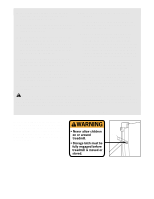
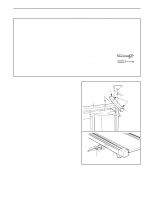
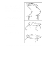
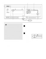
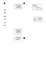
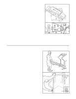
ASSEMBLY Before beginning assembly, carefully read the following information and instructions: • Assembly requires two people. • Place all parts in a cleared area and remove the packing materials; do not dispose of the packing materials until assembly is completed. • The underside of the treadmill walking belt is coated with high-performance lubricant. During shipping, a small amount of lubricant may be transferred to the top of the walking belt or the shipping carton. This is a normal condition. If there is lubricant on top of the walking belt, wipe off the lubricant with a soft cloth and a mild, nonabrasive cleaner. • The console and the right handrail are connected to the treadmill by the wire harness. (See assembly step 3.) During steps 1 and 2, be careful to avoid damaging the wire harness. • As you assemble the treadmill, be sure that all parts are oriented as shown in the drawings. The following tools (not included) are required for assembly: • Two (2) adjustable spanners • One (1) phillips screwdriver 1. With the help of a second person, carefully lay the 1 treadmill on its side. Position one of the Base Legs (55) on the base of the Upright (37) as shown. Make sure that the Base Leg Pads (31) and the Wheel (34) are in the indicated positions. Attach the Base Leg with two of the four Base Leg Bolts (28), Base Leg Washers (68), and Base Leg Nuts (61). 37 Carefully turn the treadmill onto its other side. Assemble the other Base Leg (55) as described above. With the help of a second person, carefully raise the treadmill to the upright position so the Base Legs (55) are resting flat on the floor. 34 61 2. Refer to HOW TO LOWER THE TREADMILL FOR USE on page 11. Follow step 2 on page 11 to lower the 2 treadmill. Next, attach the Left Frame Guide (66) and the Frame Guide Spacer (46) to the left side of the Frame (21) with four Screws (25). Note: Be careful not to overtighten the Screws. Make sure that the thick end of the Left Frame Guide is at the bottom. 25 46 66 Thick end 21 28 68 31 55 5
-
 1
1 -
 2
2 -
 3
3 -
 4
4 -
 5
5 -
 6
6 -
 7
7 -
 8
8 -
 9
9 -
 10
10 -
 11
11 -
12
-
13
-
14
-
15
-
16
-
17
-
18
-
19
 |
 |