Weslo Cardio Glide Plus 975 English Manual - Page 5
Cardio, Glide
 |
View all Weslo Cardio Glide Plus 975 manuals
Add to My Manuals
Save this manual to your list of manuals |
Page 5 highlights
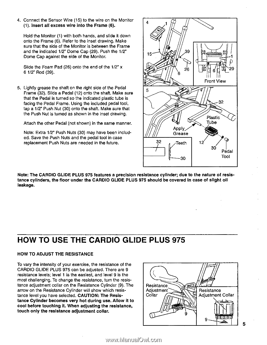
4. Connect the Sensor Wire (15) to the wire on the Monitor (1). Insert all excess wire into the Frame (6). Hold the Monitor (1) with both hands, and slide it down onto the Frame (6). Refer to the inset drawing. Make sure that the side of the Monitor is between the Frame and the indicated 1/2" Dome Cap (29). Push the 1/2" Dome Cap against the side of the Monitor. Slide the Foam Pad (26) onto the end of the 1/2" x 6 1/2" Rod (39). 5. Lightly grease the shaft on the right side of the Pedal Frame (32). Slide a Pedal (12) onto the shaft. Make sure that the Pedal is turned so the indicated plastic tube is facing the Pedal Frame. Using the included pedal tool, tap a 1/2" Push Nut (30) onto the shaft. Make sure that the Push Nut is turned as shown in the inset drawing. Attach the other Pedal (not shown) in the same manner. Note: Extra 1/2" Push Nuts (30) may have been included. Save the Push Nuts and the pedal tool in case replacement Push Nuts are needed in the future. 4 15 39 26 6 29 Front View 5 32 Apply Grease Plastic Tube (Ce:' git.p40 32 Teeth 12 30 Pedal 30 Tool Note: The CARDIO GLIDE PLUS 975 features a precision resistance cylinder; due to the nature of resistance cylinders, the floor under the CARDIO GLIDE PLUS 975 should be covered In case of slight oil leakage. HOW TO USE THE CARDIO GLIDE PLUS 975 HOW TO ADJUST THE RESISTANCE To vary the intensity of your exercise, the resistance of the CARDIO GLIDE PLUS 975 can be adjusted. There are 9 resistance levels; level 1 is the easiest, and level 9 is the most challenging. To change the resistance, turn the resis- tance adjustment collar on the Resistance Cylinder (9). The Resistance arrow on the Resistance Cylinder will show which resis- Adjustment tance level you have selected. CAUTION: The Resis- Collar tance Cylinder becomes very hot during use. Allow it to cool before touching it. When adjusting the resistance, touch only the resistance adjustment collar. 9 Resistance Adjustment Collar 9 V '7•0 1"C 5
-
 1
1 -
 2
2 -
 3
3 -
 4
4 -
 5
5 -
 6
6 -
 7
7 -
 8
8 -
 9
9 -
 10
10 -
 11
11 -
12
 |
 |