Weslo Pursuit 612s English Manual - Page 4
Attach the Lower Seat Frame 58 to the Seat Frame
 |
View all Weslo Pursuit 612s manuals
Add to My Manuals
Save this manual to your list of manuals |
Page 4 highlights
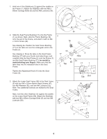
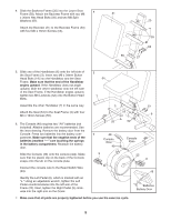
1. Hold one of the Stabilizers (2) against the saddle on the Frame (1). Attach the Stabilizer with two M8 x 1 65mm Carriage Bolts (5) and two M8 Locknuts (39). 2 5 2. Slide the Seat Frame Bushing (17) onto the Frame 2 (1) as shown. Next, slide the Frame Bushing (18) onto the end of the Frame, and attach it with an M4 x 16mm Screw (46). 1 39 16 See drawing 2a. Position the Seat Frame Bushing (17) so the tabs are over the rectangular slots in the Frame (1). See drawing 2. Press the tabs on the Seat Frame Bushing (17) with your thumb and index finger, and carefully slide the Seat Frame (3) onto the Frame (1) and the Seat Frame Bushing (17); be careful to avoid pinching your fingers. Make sure that the tabs snap into the indicated holes in the Seat Frame. 18 17 3 Hole 2a 46 Tab 17 1 1 Tighten the Adjustment Knob (16) into the Seat Frame (3). Tab Slot 3. Attach the Lower Seat Frame (58) to the Seat Frame 3 (3) with four M6 x 52mm Button Head Screws (47), four M6 Washers (35), and two M6 Locknuts (52). Note: Two additional locknuts are welded to the Seat Frame. 3 Next, hold the other Stabilizer (2) against the saddle on the Lower Seat Frame (58). Attach the Stabilizer with two M8 x 65mm Carriage Bolts (5) and two M8 Locknuts (39). 52 35 47 35 58 39 5 2 4
-
 1
1 -
 2
2 -
 3
3 -
 4
4 -
 5
5 -
 6
6 -
 7
7 -
 8
8 -
 9
9 -
 10
10 -
11
-
12
 |
 |
