Weslo Pursuit 612s English Manual - Page 5
x 36mm Hex Head Bolts 56 and two M8 Split
 |
View all Weslo Pursuit 612s manuals
Add to My Manuals
Save this manual to your list of manuals |
Page 5 highlights
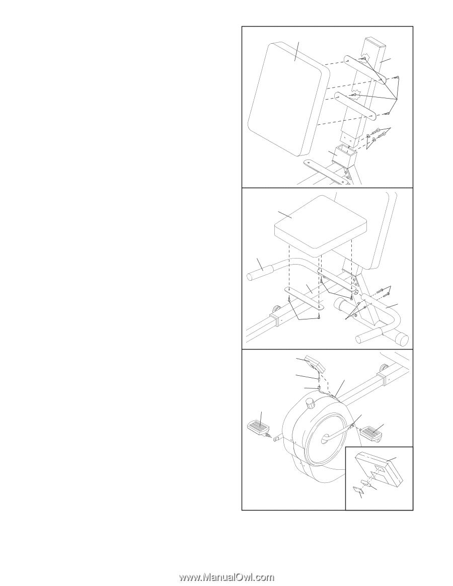
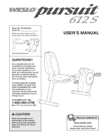
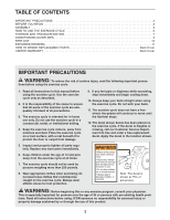
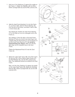
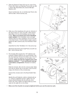
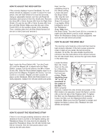
4. Slide the Backrest Frame (20) into the Lower Seat 4 Frame (58). Attach the Backrest Frame with two M8 x 36mm Hex Head Bolts (56) and two M8 Split Washers (57). Attach the Backrest (21) to the Backrest Frame (20) with four M6 x 16mm Screws (55). 21 20 55 56 58 57 5. Slide one of the Handlebars (6) onto the left side of the Seat Frame (3). Insert two M6 x 34mm Button Head Bolts (19) into the Handlebar and the Seat Frame. Make sure that the end of the Handlebar angles upward. If the Handlebar does not angle upward, slide the other Handlebar onto the left side of the Seat Frame. If the Handlebar angles upward, tighten two M6 Locknuts (52) onto the Button Head Bolts. 5 54 7 Assemble the other Handlebar (7) in the same way. Attach the Seat (54) to the Seat Frame (3) with four M6 x 16mm Screws (55). 6. The Console (48) requires two "AA" batteries (not included). Alkaline batteries are recommended. See the inset drawing. Remove the battery door from the Console. Press two batteries into the battery compartment. Make sure that the negative ends of the batteries (marked "-") are touching the springs in the battery compartment. Reattach the battery door. Slide the Console (48) onto the console plate. Make sure that the plastic clip on the back of the Console snaps onto the tab on the console plate. 3 19 55 6 55 52 6 48 Console Wire 49 9 Console Plate 22 8 Connect the console wire to the Reed Switch Wire (49). 48 Identify the Left Pedal (8), which is marked with an "L." Using an adjustable wrench, tighten the Left Pedal counterclockwise into the left arm of the Crank (22). Next, tighten the Right Pedal (9) clockwise into the right arm on the Crank. Batteries Battery Door 7. Make sure that all parts are properly tightened before you use the exercise cycle. 5
-
 1
1 -
 2
2 -
 3
3 -
 4
4 -
 5
5 -
 6
6 -
 7
7 -
 8
8 -
 9
9 -
 10
10 -
 11
11 -
12
 |
 |