Weslo Summit St65 Stepper Owners Manual - Page 6
protruding
 |
View all Weslo Summit St65 Stepper manuals
Add to My Manuals
Save this manual to your list of manuals |
Page 6 highlights
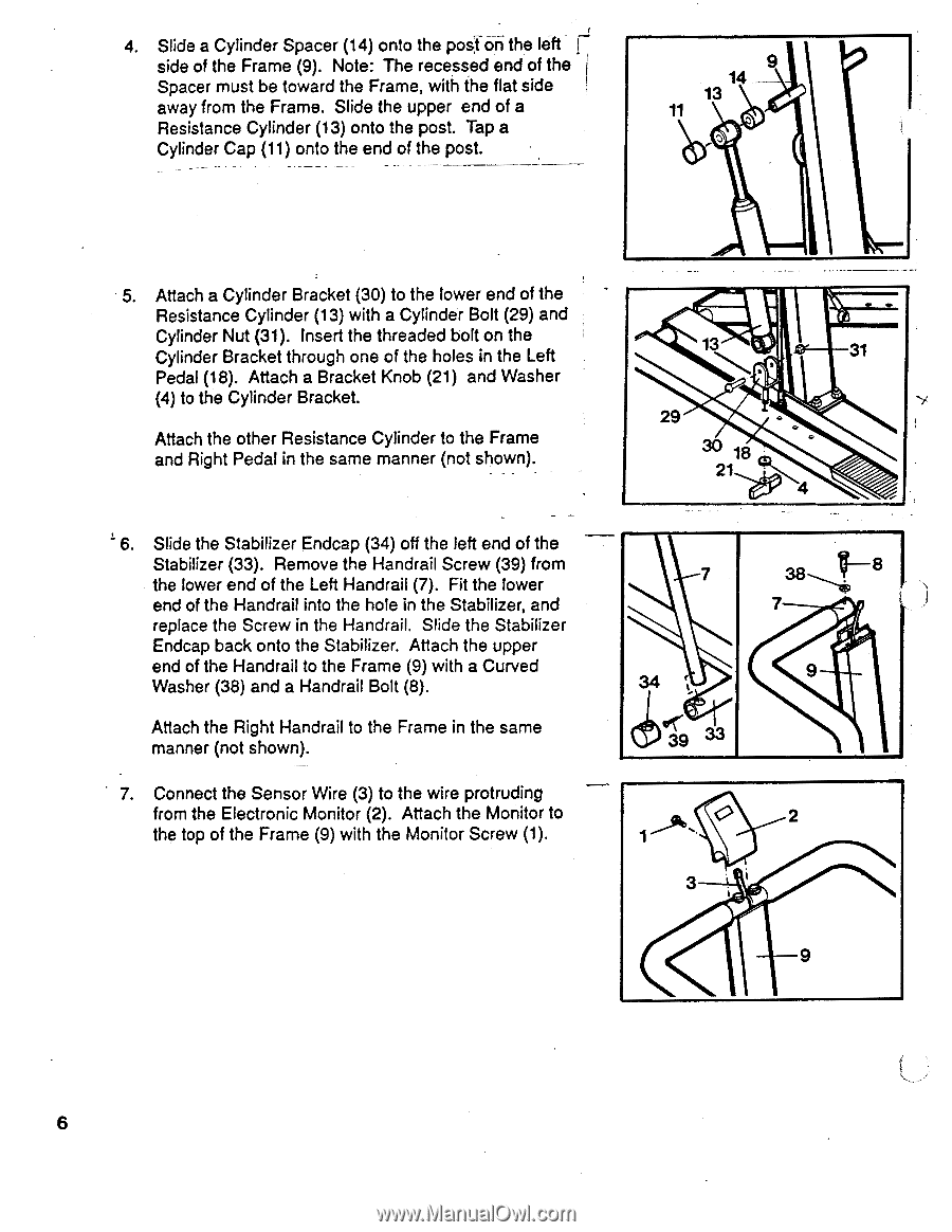
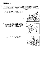
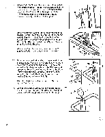
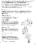
4. Slide a Cylinder Spacer (14) onto the posf•ari the left side of the Frame (9). Note: The recessed end of the Spacer must be toward the Frame, with the flat side away from the Frame. Slide the upper end of a Resistance Cylinder (13) onto the post. Tap a Cylinder Cap (11) onto the end of the post. 9 14 13 11 5. Attach a Cylinder Bracket (30) to the lower end of the Resistance Cylinder (13) with a Cylinder Bolt (29) and Cylinder Nut (31). Insert the threaded bolt on the Cylinder Bracket through one of the holes in the Left Pedal (18). Attach a Bracket Knob (21) and Washer (4) to the Cylinder Bracket. Attach the other Resistance Cylinder to the Frame and Right Pedal in the same manner (not shown). 6. Slide the Stabilizer Endcap (34) off the left end of the Stabilizer (33). Remove the Handrail Screw (39) from the lower end of the Left Handrail (7). Fit the lower end of the Handrail into the hole in the Stabilizer, and replace the Screw in the Handrail. Slide the Stabilizer Endcap back onto the Stabilizer. Attach the upper end of the Handrail to the Frame (9) with a Curved Washer (38) and a Handrail Bolt (8). Attach the Right Handrail to the Frame in the same manner (not shown). • 7. Connect the Sensor Wire (3) to the wire protruding from the Electronic Monitor (2). Attach the Monitor to the top of the Frame (9) with the Monitor Screw (1). 13 31 29 oQ 30 1 21 '1O 4 7 8 7 34 f, 9 39 33 O 2 3 9 6
-
 1
1 -
 2
2 -
 3
3 -
 4
4 -
 5
5 -
 6
6 -
 7
7 -
 8
8 -
 9
9 -
 10
10 -
 11
11 -
 12
12
 |
 |