Weslo Wlevex2715 Instruction Manual - Page 6
Maintenance And Troubleshooting
 |
View all Weslo Wlevex2715 manuals
Add to My Manuals
Save this manual to your list of manuals |
Page 6 highlights
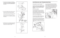
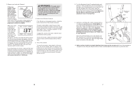
5. The Console (16) requires three 1.5V AA batteries; alkaline batteries are recommended. Insert three batteries into the Console. Make sure that the batteries are oriented as shown by the markings inside of the Console. 5 Batteries 16 6. Have a second person hold the Console (16) near the 6 Upright (13). Connect the two console wires to the Upper Wire (36) and the Pulse Sensor Wire (56). Insert the console wires, the Upper Wire (36), and the Pulse Sensor Wire (56) down into the Upright (13). Attach the Console (16) to the Upright (13) with four M4 x 12mm Screws (49). Be careful to avoid pinching the wires. 7. Attach the Seat (12) to the Seat Post (5) with three M8 7 Nylon Locknuts (10) and three M8 Flat Washers (51). Note: The Nylon Locknuts and Flat Washers may be preattached to the underside of the Seat. 16 Console Wires 56 49 36 13 Be careful to avoid pinching the wires. 12 5 51 10 51 10 6 MAINTENANCE AND TROUBLESHOOTING Inspect and tighten all parts of the exercise cycle regularly. Replace any worn parts immediately. To clean the exercise cycle, use a damp cloth and a small amount of mild detergent. Important: To avoid damage to the console, keep liquids away from the console and keep the console out of direct sunlight. BATTERY REPLACEMENT If the console display becomes dim, the batteries should be replaced; most console problems are the result of low batteries. To replace the batteries, first see step 6 on page 6 and remove the console from the upright. Next, see step 5 and insert three batteries into the console. Reattach the console to the upright, being careful not to pinch the wires. HOW TO ADJUST THE REED SWITCH If the console does not display correct feedback, the reed switch should be adjusted. To adjust the reed switch, the left side shield must be removed. Turn the Crank (35) to the position shown. Using an adjustable spanner, turn the Left Pedal (24) clockwise and remove it. Next, remove the five M5 x 25mm Screws (52) and the M5 x 20mm Screw (42) from the Left Side Shield (17). Carefully remove the Left Side Shield. Next, locate the Reed Switch (43). Turn the Crank (35) until the Magnet (38) is aligned with the Reed Switch. Loosen, but do not remove, the M5 x 15mm Screw (46). Slide the Reed Switch slightly closer to or away from the Magnet, and then retighten the Screw. Turn the Crank for a moment. Repeat until the console displays correct feedback. When the Reed Switch is correctly adjusted, reattach the left side shield and the left pedal. 35 46 43 38 52 24 35 42 17 52 11
-
 1
1 -
 2
2 -
 3
3 -
 4
4 -
 5
5 -
 6
6 -
 7
7 -
 8
8
 |
 |
