Whirlpool GLS3064RS Installation Instructions - Page 7
Complete Installation - manual
 |
UPC - 883049003566
View all Whirlpool GLS3064RS manuals
Add to My Manuals
Save this manual to your list of manuals |
Page 7 highlights
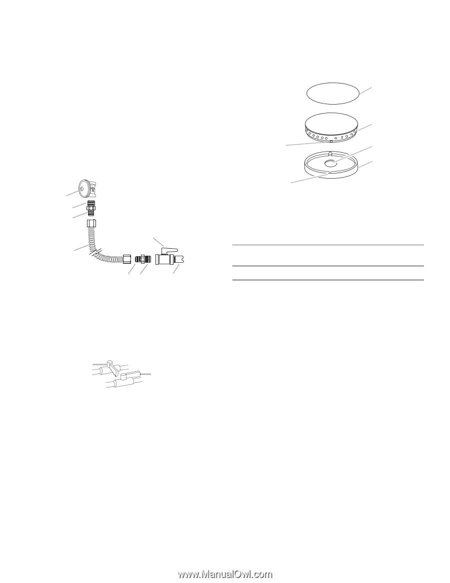
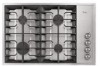
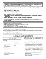
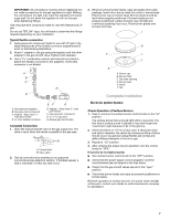
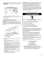
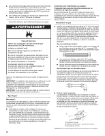
IMPORTANT: All connections must be wrench-tightened. Do not make connections to the gas regulator too tight. Making the connections too tight may crack the regulator and cause a gas leak. Do not allow the regulator to turn on the pipe when tightening fittings. Use only pipe-joint compound made for use with Natural and LP gas. Do not use TEFLON®† tape. You will need to determine the fittings required depending on your installation. Typical flexible connection 1. Apply pipe-joint compound made for use with LP gas to the larger thread ends of the flexible connector adapters (see B and F in the following illustration). 2. Attach 1 adapter to the gas pressure regulator and the other adapter to the gas shutoff valve. Tighten both adapters. 3. Use a combination wrench and channel lock pliers to attach the flexible connector to the adapters. Check that connector is not kinked. A B C H D A. Gas pressure regulator B. Use pipe-joint compound C. Adapter - Must have ½" male pipe thread D min. flexible connector EF G E. Adapter - Must have ½" male pipe thread F. Use pipe-joint compound. G. ½" or ¾" gas pipe H. Manual gas shutoff valve Complete Connection 1. Open the manual shutoff valve in the gas supply line. The valve is open when the handle is parallel to the gas pipe. A B A. Closed valve B. Open valve 2. Test all connections by brushing on an approved noncorrosive leak-detection solution. If bubbles appear, a leak is indicated. Correct any leak found. 3. Remove surface burner heads, caps and grates from parts package. Insert tab in burner head into notch in burner base. Place burner cap on burner head. Burner heads should be level when properly positioned. If burner heads are not properly positioned, surface burners may not light and continuous sparking may occur. Place burner grates over burners and caps. A B F C D E A. Burner cap B. Burner head C. Gas tube opening D. Burner base E. Notch F. Tab Complete Installation Electronic Ignition System Check Operation of Surface Burners 1. Push in and turn the surface burner control knobs to the "HI" position. The surface burner flame should light within 4 seconds. The first time a surface burner is lighted it may take longer that 4 seconds to light because of air in the gas line. 2. Check the flame on "HI" for a blue color. It should be clean and soft in character. No yellow tip, blowing or lifting of flame should occur. Occasional orange flashes are normal and reflect different elements in the air or gas. 3. Repeat at "LO" position. 4. After verifying the proper burner operation, turn the control knobs to "OFF." If burners do not light properly: ■ Turn surface burner control knob to the "OFF" position. ■ Check that the power supply cord is plugged in and the circuit breaker has not tripped or the fuse blown. ■ Check that the gas shutoff valves are set to the "open" position. ■ Check that burner heads and caps are properly positioned on burner bases. Recheck operation of surface burners. If a burner does not light at this point, contact your dealer or authorized service company for assistance. 7
-
 1
1 -
 2
2 -
 3
3 -
 4
4 -
 5
5 -
 6
6 -
 7
7 -
 8
8 -
 9
9 -
 10
10 -
 11
11 -
 12
12 -
13
-
14
-
15
-
16
 |
 |