Whirlpool LDR3822PQ Owners Manual - Page 4
Installation Instructions - manual
 |
UPC - 050946958309
View all Whirlpool LDR3822PQ manuals
Add to My Manuals
Save this manual to your list of manuals |
Page 4 highlights
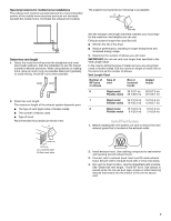
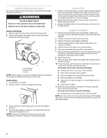
INSTALLATION INSTRUCTIONS Tools and Parts Tools needed Gather the required tools and parts before starting installation. Read and follow the safety instructions provided with any tools listed here. s Flat-blade screwdriver s Level s Adjustable wrench s Vent clamps s Caulking gun and compound (for installing new exhaust vent) s Tin snips (new vent installations) Parts supplied Remove parts package from the dryer drum. Check that all parts listed are included. s 1 - Cycle Control (timer) knob s 1 - Push to Start button s 2 - cord brackets s 2 - screws s 4 - casters s A grounded electrical outlet located within 2 ft (61 cm) of either side of the dryer. See "Electrical Requirements." s A sturdy floor to support the dryer weight (dryer and load) of 115 lbs (52 kg). The combined weight of a companion appliance should also be considered. s A level floor with a maximum slope of 1" (2.5 cm) under entire dryer. Do not operate your dryer at temperatures below 45ºF (7ºC). At lower temperatures, the dryer might not shut off at the end of an automatic cycle. Drying times can be extended. The dryer must not be installed or stored in an area where it will be exposed to water and/or weather. Check code requirements. Some codes limit, or do not permit, installation of the dryer in garages, closets, mobile homes, or sleeping quarters. Contact your local building inspector. Installation Clearances The location must be large enough to allow the dryer door to open fully. Dryer Dimensions Parts needed Check local codes, existing electrical supply and venting, and see "Venting Requirements" and "Electrical Requirements" before purchasing parts. s Mobile home installations require metal exhaust system hardware s Permanent installations require 4 dryer feet For ordering information, please reference the "Assistance or Service" section of this manual. You can also contact the dealer from whom you purchased your dryer. *20 3 4" (52.7 cm) 31"† (78.7 cm) Location Requirements WARNING 23 7 8" (60.6 cm) †Height with caster is 32½" (82.6 cm) *Most installations require a minimum 5½" (14.0 cm) clearance behind the dryer for the exhaust vent with elbows. See "Venting Requirements." Explosion Hazard Keep flammable materials and vapors, such as gasoline, away from dryer. Place dryer at least 18 inches (46 cm) above the floor for a garage installation. Failure to do so can result in death, explosion, or fire. You will need s A location that allows for proper exhaust installation. See "Venting Requirements." s A 120-volt, 60-hz., AC-only, 15- or 20-amp circuit. Minimum installation spacing for recessed area and closet installation The following dimensions shown are for the minimum spacing allowed when the unit is to be operated with, or without, the Stack Stand Kit. To purchase a Stack Stand Kit, see "Assistance or Service." s Additional spacing should be considered for ease of installation and servicing. s Additional clearances might be required for wall, door, and floor moldings. s Additional spacing of 1" (2.5 cm) on all sides of the dryer is recommended to reduce noise transfer. s For closet installation with a door, minimum ventilation openings in the top and bottom of the door are required. Louvered doors with equivalent ventilation openings are acceptable. s Companion appliance spacing should also be considered. 4
-
 1
1 -
 2
2 -
 3
3 -
 4
4 -
 5
5 -
 6
6 -
 7
7 -
 8
8 -
 9
9 -
 10
10 -
11
-
12
-
13
-
14
-
15
-
16
-
17
-
18
-
19
-
20
-
21
-
22
-
23
-
24
-
25
-
26
-
27
-
28
 |
 |
