Whirlpool UXD8630DY Owners Manual - Page 16
Make Electrical Connections, Check Operation
 |
View all Whirlpool UXD8630DY manuals
Add to My Manuals
Save this manual to your list of manuals |
Page 16 highlights
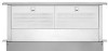
Make Electrical Connections WARNING Electrical Shock Hazard Disconnect power before servicing. Replace all parts and panels before operating. Failure to do so can result in death or electrical shock. 1. Disconnect power. 2. Feed the power supply cable through the conduit connector and into the terminal box. WARNING Electrical Shock Hazard Electrically ground blower. Connect ground wire to green and yellow ground wire in terminal box. Failure to do so can result in death or electrical shock. 3. Connect the green (or green/yellow) ground wire to the green or yellow/green ground wire using UL listed wire connectors. Tighten the screw on the conduit connector. 4. Connect the 2 white wires together using UL listed wire connectors. FC D E Check Operation 1. Push and hold the button on the top of the downdraft vent for a few seconds. The retractable section of the downdraft vent will rise and the blower will be able to start using the control slider. Remove any protective film and use a stainless steel cleaner to clean any remaining grease. Position the top trim over the retractable section and snap trim into place. Trim kits for matching your cooktop color are available from your dealer. For information on ordering, see the "Assistance or Service" section. B A C E D A. Top trim B. On/Off button C. Blower control slider D. End cap E. Filters 2. Slide the control slider on the side of vent to check the operation and speed of the blower. 3. If the blower does not operate: ■■ Check that filter or filters are pressed in as far as they will go. ■■ Check that the circuit breaker has not tripped or a household fuse blown. 4. Connect vent system to blower. Vent system must end with a wall or roof cap. Use clamps or duct tape to seal all joints. 5. Install cooktop according to manufacturer's instructions. Check that rear of cooktop overlaps edge of retractable downdraft vent by 3/8" (9.5 mm). See "Countertop Cutout Dimensions" in the "Location Requirements" section. NOTE: To get the most-efficient use from your new retractable downdraft vent, read the "Vent System Use" section. B A A. Green or green and yellow ground wire B. White wires C. UL listed wire connectors D. Black wires E. UL listed or CSA approved conduit connector F. Downdraft vent wiring 5. Connect the 2 black wires together using UL listed wire connectors. 6. Replace the terminal box cover and secure with screw. 7. Reconnect power. 16
-
 1
1 -
2
-
3
-
4
-
5
-
6
-
7
-
8
-
9
-
10
-
 11
11 -
 12
12 -
 13
13 -
 14
14 -
 15
15 -
 16
16 -
 17
17 -
 18
18 -
 19
19 -
 20
20 -
 21
21 -
22
-
23
-
24
-
25
-
26
-
27
-
28
-
29
-
30
-
31
-
32
-
33
-
34
-
35
-
36
-
37
-
38
-
39
-
40
-
41
-
42
-
43
-
44
 |
 |
