Whirlpool UXD8636DYS Installation Guide - Page 12
Complete Installation
 |
View all Whirlpool UXD8636DYS manuals
Add to My Manuals
Save this manual to your list of manuals |
Page 12 highlights
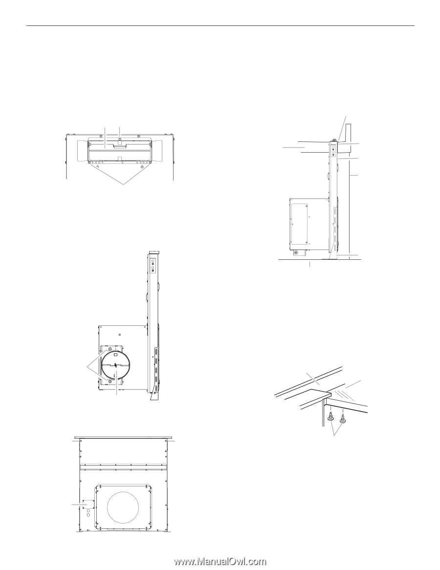
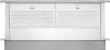
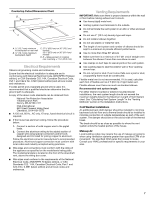
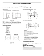
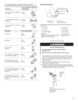
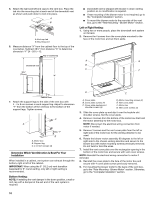
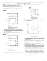
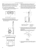
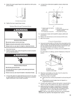
Complete Installation NOTE: The downdraft vent system is supplied with a 3¹⁄₄" x 10" (8.3 x 25.4 cm) back draft damper and a 6" (15.2 cm) round vent transition with damper. Refer to "3¹⁄₄" x 10" (8.3 x 25.4 cm) back draft damper" or "6" (15.2 cm) round vent transition with damper," depending upon the type of venting you are using. 3¹⁄₄" x 10" (8.3 x 25.4 cm) Back Draft Damper 1. Attach the 3¼" x 10" (8.3 x 25.4 cm) back draft damper to the vent opening in the blower motor box, using three 3.5 x 9.5 mm screws. 3. Determine which direction (front or rear) the home power supply cable will enter the terminal box. Remove the appropriate knockout from the front or rear panel and install a ¹⁄₂" (12.7 mm) UL listed or CSA approved conduit connector. 4. Using 2 or more people, insert the downdraft vent into the countertop cutout. Position downdraft vent so it is centered in the cutout with the rear flange over the edge of the cutout and the rear of the vent box against the edge of the cutout. A BA A A. 3.5 x 9.5 mm screws B. 3¼" x 10" (8.3 x 25.4 cm) back draft damper 6" (15.2 cm) Round Vent Transition With Damper 1. Attach the 6" (15.2 cm) round vent transition to vent opening (left or right side venting only is recommended), using two 3.5 x 9.5 mm screws. A G B C D E F A. Rear flange of downdraft vent B. Edge of cutout in countertop C. Rear of downdraft vent D. Cabinet back E. Lower support leg F. Cabinet floor G. Countertop 5. Drill 2 pilot holes through each of the undercounter mounting brackets into the underside of the countertop. Using 2 screws (not provided) of the appropriate length, mount the brackets to the countertop. IMPORTANT: Select a screw length that will not allow the screws to go through the countertop when tightened. B C B A. 3.5 x 9.5 mm screws B. 6" (15.2 cm) round vent transition with damper 2. Remove 4 screws attaching the terminal box cover. A A A. Screws B. Backsplash C. Countertop 6. Check that the downdraft vent is level vertically. Loosen the lower support legs screws and position the legs against the cabinet floor. A. Terminal box cover 12
-
 1
1 -
2
-
3
-
4
-
5
-
6
-
 7
7 -
 8
8 -
 9
9 -
 10
10 -
 11
11 -
 12
12 -
 13
13 -
 14
14 -
 15
15 -
 16
16 -
 17
17 -
18
-
19
-
20
-
21
-
22
-
23
-
24
-
25
-
26
-
27
-
28
-
29
-
30
-
31
-
32
-
33
-
34
-
35
-
36
 |
 |