Whirlpool UXD8636DYS Dimension Guide - Page 1
Whirlpool UXD8636DYS Manual
 |
View all Whirlpool UXD8636DYS manuals
Add to My Manuals
Save this manual to your list of manuals |
Page 1 highlights
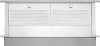
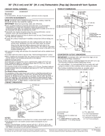
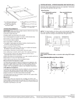
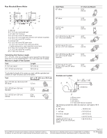
30" (76.2 cm) and 36" (91.4 cm) Retractable (Pop-Up) Downdraft Vent System PRODUCT MODEL NUMBERS PRODUCT DIMENSIONS UXD8630DY UXD8636DY Electrical A 120 Volt, 60 Hz., AC only 15-amp fused, electrical circuit is required. LOCATION REQUIREMENTS NOTE: Downdraft vent is installed directly behind the cooktop. Install the downdraft vent first, then install the cooktop. IMPORTANT: Observe all governing codes and ordinances. q Have a qualified technician install the downdraft vent. It is the installer's responsibility to comply with installation clearances specified on the model/serial rating plate. The model/serial rating plate is located on the front of the downdraft vent above the terminal box cover. q Downdraft vent location should be away from strong draft areas, such as windows, doors, and strong heating vents or fans. q Cabinet opening dimensions that are shown must be used. Given dimensions provide minimum clearance. q Consult the cooktop manufacturer installation instructions before making any cutouts. Check that the downdraft vent and cooktop location will clear the cabinet walls, backsplash, and rear wall studs inside the cabinet. Check for the minimum distance between the front edge of the countertop and the front edge of the cooktop. The minimum horizontal distance between the overhead cabinets is the same as the width of the installed downdraft vent. q All openings in ceiling and wall where the downdraft vent will be installed must be sealed. q Grounded electrical outlet is required. See "Electrical Requirements" section. q When installing the downdraft vent, the cabinet drawer will need to be removed and the drawer front installed permanently to the cabinet. Cabinet Construction: Downdraft vent is designed for use in a cabinet with a depth of 24" (61 cm). Some installations require a countertop deeper than 25" (63.5 cm). See the Countertop Cutout Dimensions section. The maximum depth of the overhead cabinet is 13" (33 cm). Overhead cabinets installed at either side of the downdraft vent must be 18" (45.7 cm) above the cooking surface. For Mobile Home Installations The installation of this range hood must conform to the Manufactured Home Construction Safety Standards, Title 24 CFR, Part 328 (formerly the Federal Standard for Mobile Home Construction and Safety, title 24, HUD, Part 280) or when such standard is not applicable, the standard for Manufactured Home Installation 1982 (Manufactured Home Sites, Communities and Setups) ANSI A225.1/NFPA 501A*, or latest edition, or with local codes. CABINET DIMENSIONS 13¹⁄₂" (34.3 cm) retractable vent height Top trim widths: 30" (76.2 cm) 36" (91.4 cm) 27" (68.6 cm) for 30" (76.2 cm) vent 33" (83.8 cm) for 36" (91.4 cm) vent 1¹⁄₂" (3.8 cm 0.95 cm) 13¹⁄₈" (33.4 cm) 5¹⁄₄"(13.3 cm) for 30" (76.2 cm) vent 8¹⁄₄"(21.0 cm) for 36" (91.4 cm) vent 28¹⁄₂" (72.4 cm) ³⁄₄ (1.9 cm) 16¹⁄₂" (42.0 cm) 10" (25.4 cm) 2¹⁄₈" (5.4 cm) COUNTERTOP CUTOUT DIMENSIONS IMPORTANT: Countertops with a bull-nosed front edge are not recommended for these installations. q Some models require a countertop deeper than 25" (63.5 cm); see the following Countertop Cutout Dimensions section. q To avoid mistakes, it is recommended that the cooktop and vent cutouts be drawn on the countertop before making any cutouts. q See Cooktop Installation Instructions for complete cutout dimensions, location dimensions and installation details. D E F B C 10" (25.4 cm) G A 12.7 mm) minimum H 21 54.1 cm) 21 54.1 cm) Cutouts are for 3¹⁄₄" x 10" (8.3 x 25.4 cm) rectangular or 6" (15.2 cm) round vent system. NOTES: Locate power supply junction box at lower left hand rear corner of the cabinet. Centerline of cooktop cutout q See cooktop manufacturer's instructions for cooktop cutout depth and width. q Use dimensions for vent system cutout location that applies to your installation. q Interior mounted blower systems connect with 3¹⁄₄" x 10" (8.3 x 25.4 cm) rectangular or 6" (15.2 cm) round vent system. The cutout locations for this vent system will depend on your specific installation. A I A. Downdraft vent B. Cooktop C. Measurement of cooktop rear overhang. D. D = Measurement of cooktop rear overhang (C) + 1 46.2 mm] (E) E. 1 46.2 mm) F. ½" (12.7 mm) minimum G. ¼" (6.4 mm) minimum H. Countertop and backsplash I. ½" (12.7 mm) minimum Page 1 of 3 Because Whirlpool Corporation policy includes a continuous commitment to improve Dimensions are for planning purposes only. For complete details, see Installation our products, we reserve the right to change materials and specifications without notice. Instructions packed with product. Specifications subject to change without notice. Ref. W10342491C 2/8/2012
-
 1
1 -
 2
2 -
 3
3
 |
 |