Whirlpool UXD8636DYS Dimension Guide - Page 2
Front Standard Mounted Blower Motor - parts
 |
View all Whirlpool UXD8636DYS manuals
Add to My Manuals
Save this manual to your list of manuals |
Page 2 highlights
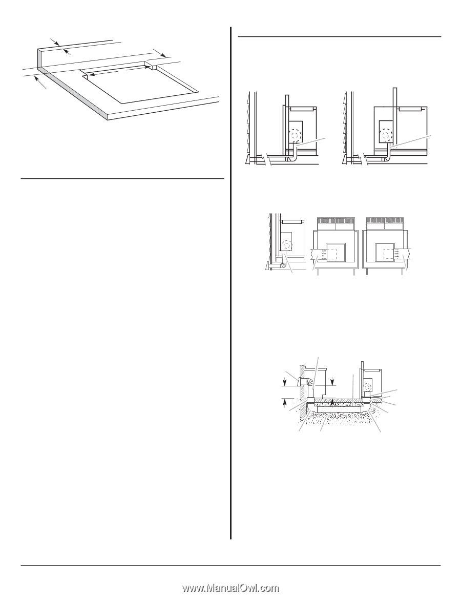
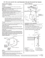
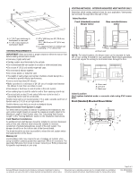
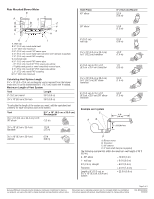
B D C A VENTING METHODS - INTERIOR MOUNTED VENT MOTOR ONLY Determine which venting method is best for your application. Vent system can terminate through either the wall or floor. Island location Front (standard) mounted blower motor Rear mounted blower motor A. ½" (12.7 mm) minimum to backsplash or rear wall B 19.1 mm) maximum backsplash depth VENTING REQUIREMENTS C. 27¹⁄₂" (69.9 cm) on 30" (76.2 cm) models 33¹⁄₂" (85.9 cm) on 36" (91.4 cm) models D. D = Measurement of cooktop rear overhang + 1 46.2 mm) IMPORTANT: Make sure there is proper clearance within the wall or floor before making exhaust vent cutouts. q Use heavy (rigid) metal vent. q Venting system must terminate to the outside. q Do not terminate the vent system in an attic or other enclosed area. q Do not use 4" (10.2 cm) laundry-type wall caps. q Do not install 2 elbows together. q Do not use plastic or metal foil vent. q The length of vent system and number of elbows should be kept to a minimum to provide efficient performance. q Use no more than three 90° elbows q Make sure there is a minimum of 24" (61 cm) of straight vent between the elbows if more than one elbow is used. q Use clamps or duct tape to seal all joints in the vent system. q Use caulking tape to seal the exterior wall or floor opening around cap. q Do not cut joist or stud. If vent cutout falls over a joist or stud, a supporting frame must be constructed. Flexible metal vent is not recommended. If it is used, calculate each foot of flexible vent as 2 ft (0.6 m) of rigid metal vent. Flexible elbows count twice as much as standard elbows. Recommended Vent System Length: For either interior-mounted or exterior-mounted blower installations, the vent system length should not exceed the maximum lengths listed in the Maximum Length of Vent System chart. See "Calculating Vent System Length" in the "Venting Methods" section in the Installation Instructions. Cold Weather Installations An additional back draft damper should be installed to minimize backward cold air flow and a thermal break should be installed to minimize conduction of outside temperatures as part of the vent system. The damper should be on the cold air side of the thermal break. The break should be as close as possible to where the vent system enters the heated portion of the house. Makeup Air Local building codes may require the use of makeup air systems when using ventilation systems greater than specified CFM of air movement. The specified CFM varies from locale to locale. Consult your HVAC professional for specific requirements in your area. A A A. Down vent NOTE: For island locations, the blower motor can be mounted for right, left, or rear venting if needed for your application. Most island applications would still require the venting to be directed down through the floor. AB C A. Down vent B. Left vent C. Right vent Island Location Vent system installed under a concrete slab using PVC sewer pipe. Front (Standard) Mounted Blower Motor B A D M C E F G L H K J I Because Whirlpool Corporation policy includes a continuous commitment to improve Dimensions are for planning purposes only. For complete details, see Installation our products, we reserve the right to change materials and specifications without notice. Instructions packed with product. Specifications subject to change without notice. Page 2 of 3 Ref. W10342491C 2/8/2012
-
 1
1 -
 2
2 -
 3
3
 |
 |