Whirlpool UXL6036YSS Installation Guide - Page 10
Warning
 |
View all Whirlpool UXL6036YSS manuals
Add to My Manuals
Save this manual to your list of manuals |
Page 10 highlights
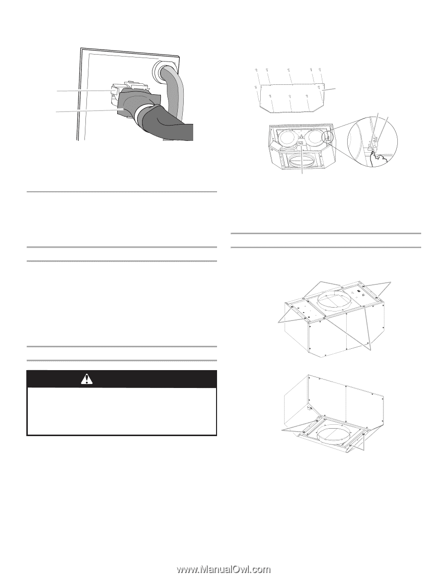
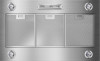
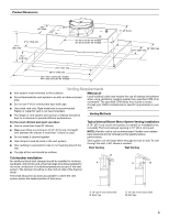
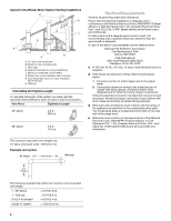
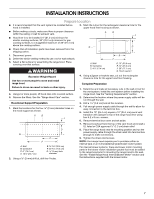
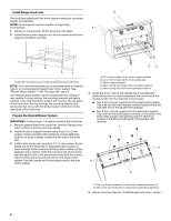
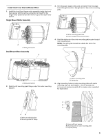
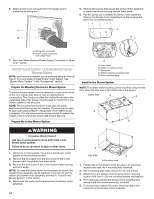
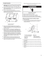
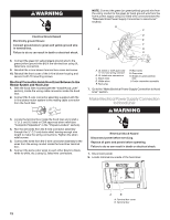
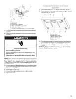
6. Attach power cord connector from the range hood to connector on wiring box. A B 5. Remove the screws that secure the blower motor assembly to the in-line blower housing and set them aside. 6. Pull the spring clip to release the blower motor assembly. Remove the blower motor assembly from the housing and place it on a covered surface. A BC A. Wiring box connector B. Power supply connector from range hood 7. Go to the "Make Electrical Power Supply Connection to Hood Liner" section. Install Hood Liner In-Line (External Type) Blower Motor NOTE: Your hood liner requires you to purchase either an internal type or an in-line (external type) blower motor system. See "Blower Motor System" in the "Accessories" section. Prepare for Mounting the In-Line Blower System The in-line blower system must be fastened to a secure structure of the roof, ceiling, wall, floor, or new or existing frame construction. The 4 holes on either the inlet (bottom) side or the outlet (top) side of the blower must be used to mount the in-line blower system to the structure. NOTE: The mounting hole locations must span the studs. Additional stud framing may be required. Plywood may be used to span open areas between ceiling joists or roof rafters to aid installation. This structure must be strong enough to support the weight of the in-line blower system (50 lb [22.6 kg] min). Prepare the In-line Blower System D A. Front cover B. Blower mounting screws C. Spring clip D. Bottom housing mounting holes E. Motor electrical plug Install In-line Blower System NOTE: The blower motor housing can be mounted using 4 holes from either the inlet side or the outlet side of the blower. Outlet Side A A A A WARNING Excessive Weight Hazard Use two or more people to move and install in-line blower motor system. Failure to do so can result in back or other injury. 1. Using two or more people, move the in-line blower motor system to the mounting location. 2. Remove the 10 screws from the front cover of the in-line blower motor housing and set them aside. 3. Remove the front cover of the in-line blower motor housing and set it aside. NOTE: To make the blower motor housing easier to mount, the blower motor assembly can be removed. If you do not want to remove the blower motor assembly, proceed to "Install In-line Blower System" in this section. 4. Disconnect the motor electrical plug from the blower motor assembly. 10 A Inlet Side A A. Mounting holes 1. Position the in-line blower motor housing in its mounting location and mark the 4 mounting hole locations. 2. Drill 4 mounting pilot holes using a 5 mm) drill bit. 3. Attach the in-line blower motor housing to the mounting location with four 6 x 80 mm mounting screws and washers. 4. If it is removed, reinstall the blower motor assembly and secure it with the screws previously removed. 5. If it is removed, reattach the motor electrical plug to the connector on the blower motor assembly.
-
 1
1 -
2
-
3
-
4
-
 5
5 -
 6
6 -
 7
7 -
 8
8 -
 9
9 -
 10
10 -
 11
11 -
 12
12 -
 13
13 -
 14
14 -
 15
15 -
16
-
17
-
18
-
19
-
20
-
21
-
22
-
23
-
24
-
25
-
26
-
27
-
28
-
29
-
30
-
31
-
32
-
33
-
34
-
35
-
36
 |
 |