Whirlpool UXL6036YSS Installation Guide - Page 12
Make Electrical Power Supply Connection, to Hood Liner
 |
View all Whirlpool UXL6036YSS manuals
Add to My Manuals
Save this manual to your list of manuals |
Page 12 highlights
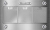
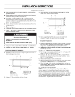
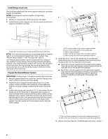
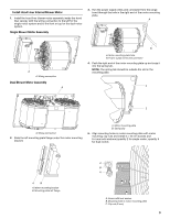
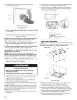
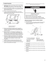
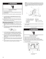
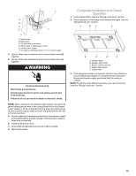
WARNING Electrical Shock Hazard Electrically ground blower. Connect ground wire to green and yellow ground wire in terminal box. Failure to do so can result in death or electrical shock. NOTE: Connect the green (or green/yellow) ground wire from the wiring conduit to the green (or bare) ground wire from the home power supply using UL listed wire connectors (see the "Make Electrical Power Supply Connection to Hood Liner" section). B C D E F A G H 8. Connect the green (or yellow/green) ground wire to the green/yellow ground wire (H) in the terminal box using UL listed wire connectors. 9. Reinstall the in-line blower terminal box cover and screw. 10. Reinstall the front cover of the in-line blower housing and secure it with 10 mounting screws. Electrical Connection Inside Hood Liner Between In-line Blower System and Hood Liner 1. With the hood liner mounted (see the "Install Hood Liner" section), locate the wiring cable connector inside the hood liner. 2. Connect the 6-wire connector assembly supplied with the in-line blower motor system to the mating cable connector from the hood liner. I A. UL listed or CSA approved ¹⁄₂" (1.3 cm) wiring conduit B. UL listed wire connectors C. Black wires D. White wires E. Red wires F. Blue wires G. Gray wires H. Green (or green/yellow) wire I. 6-wire connector assembly 7. Go to the "Make Electrical Power Supply Connection to Hood Liner" section. Make Electrical Power Supply Connection to Hood Liner WARNING 3. Locate the terminal box inside the hood liner and install a ¹⁄₂" (1.3 cm) UL listed or CSA approved strain relief (see "Complete Preparation" in the "Prepare Location" section). 4. Run the wire ends from the 6-wire connector assembly through the ¹⁄₂" (1.3 cm) strain relief, leaving enough wire length to make the wiring connections. Tighten the strain relief screws. 5. Connect the wires from the 6-wire connector assembly to the wires from the wiring conduit inside the hood liner terminal box. 6. Connect the same color wires to each other (black to black, white to white, etc.) using UL listed wire connectors. Electrical Shock Hazard Disconnect power before servicing. Replace all parts and panels before operating. Failure to do so can result in death or electrical shock. 1. Disconnect power. 2. Locate terminal box inside of the hood liner. A B A. Terminal box cover B. Terminal box 12
-
 1
1 -
2
-
3
-
4
-
5
-
6
-
 7
7 -
 8
8 -
 9
9 -
 10
10 -
 11
11 -
 12
12 -
 13
13 -
 14
14 -
 15
15 -
 16
16 -
 17
17 -
18
-
19
-
20
-
21
-
22
-
23
-
24
-
25
-
26
-
27
-
28
-
29
-
30
-
31
-
32
-
33
-
34
-
35
-
36
 |
 |