Whirlpool UXT4030AYB Use & Care Guide - Page 8
Range Hood Use
 |
View all Whirlpool UXT4030AYB manuals
Add to My Manuals
Save this manual to your list of manuals |
Page 8 highlights
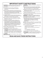
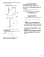
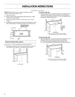
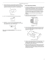
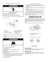
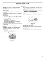
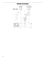
Make Electrical Connection WARNING Electrical Shock Hazard Disconnect power before servicing. Replace all parts and panels before operating. Failure to do so can result in death or electrical shock. 1. Disconnect power. G C D E A B F Complete Installation 1. Install the 75W (max.) Incandescent light bulb. See "Replacing the Incandescent Light Bulb" in the "Range Hood Care" section. 2. Replace grease filter if removed. See the "Range Hood Care" section. 3. Check the operation of the range hood fan and light. See "Range Hood Use" section. If range hood does not operate, check to see whether a circuit breaker has tripped or a household fuse has blown. Disconnect power and check wiring connections. NOTE: To get the most efficient use from your new range hood, read the "Range Hood Use" section. RANGE HOOD USE The range hood is designed to remove smoke, cooking vapors and odors from the cooktop area. For best results, start the hood before cooking and allow it to operate several minutes after the cooking is complete to clear all smoke and odors from the kitchen. The hood controls are located on the top of the range hood. A A. White wires B. Black wires C. UL listed wire connector D. Green (or bare) ground wire E. Home power supply cable or power cord accessory kit F. UL listed or CSA approved ½" strain relief G. Green ground screw 2. Use UL listed wire connectors and connect white wires (A) together. 3. Use UL listed wire connectors and connect black wires (B) together. WARNING B C A. Incandescent light housing and cover B. Charcoal filter retainer C. Grease filter Range Hood Controls Off On Off Low High Fire Hazard Electrically ground the blower. Use copper wire. Connect ground wire to green ground screw in terminal box. Failure to do so can result in death, fire, or electrical shock. 4. Connect green (or bare) ground wire from power supply to green ground screw in terminal box and securely tighten. 5. Install terminal box cover. 6. Reconnect power. 8 A B A. On/Off light switch B. Fan speed switch Operating the light Push the light switch to the right to turn the light Off. Push the light switch to the left to the turn the light On. Operating the fan Push the fan switch to the left for Low speed. Push the fan switch to the right for High speed. Push the fan switch to the middle for Off.
-
 1
1 -
2
-
 3
3 -
 4
4 -
 5
5 -
 6
6 -
 7
7 -
 8
8 -
 9
9 -
 10
10 -
 11
11 -
 12
12 -
 13
13 -
14
-
15
-
16
-
17
-
18
-
19
-
20
-
21
-
22
-
23
-
24
 |
 |