Whirlpool UXT5230BD Installation Instructions - Page 7
Mark and Cut Vent Opening, Drill Electrical Opening
 |
View all Whirlpool UXT5230BD manuals
Add to My Manuals
Save this manual to your list of manuals |
Page 7 highlights
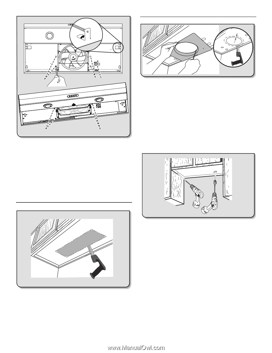
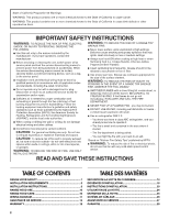
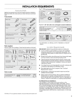
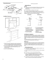
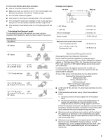
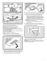
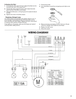
A 90˚ 7" (17.8 cm) Round Vent System 1" (2.5 cm) A C CB D D Hold the range hood firmly in place with one hand and bend each mounting tab (A) upward approximately 90°. Mark the hole at the power supply knockout (B). OPTIONAL: Mark the hole in each mounting tab. For a non-vented (recirculating) installation: Go to Step 7. For a top vented installation: Mark the 4 vent hole locations (C) on the top of the range hood. For a rear vented installation: Mark the 4 vent hole locations (D) on the rear of the range hood. Remove the range hood and set it aside. 6. Mark and Cut Vent Opening 3¹⁄₄" x 10" (8.3 x 25.4 cm) Rectangular Vent System ■ Using the 7" (17.8 cm) round vent mounting plate, draw the vent opening outline on the underside of the cabinet: - Place the vent mounting plate on the bottom of the cabinet. Position the edge of the plate with the widest distance (A) between the hole and edge of the mounting plate against the wall. Position the side edges of the mounting plate between the dots marked previously. IMPORTANT: The widest edge (A) of the vent mounting plate must be positioned against the wall. - Trace the 7" (17.8 cm) vent opening (solid line) on the cabinet bottom. ■ Using a jigsaw or keyhole saw, cut the vent opening 1" (2.5 cm) larger than the 7" (17.8 cm) hole traced (dashed line). 7. Drill Electrical Opening Using a 1¹⁄₄" (3 cm) drill bit, drill the hole in the dot marked previously at the electrical strain relief. OPTIONAL: Using a ¹⁄₈" (3 mm) drill bit, drill pilot holes for the dots marked previously at each mounting tab at an approximate 45° angle in an upward direction. ■ Using a ¹⁄₂" (13 mm) drill bit, drill a hole in each of the dots marked previously on either the wall or upper cabinet. Using the outside edges of the holes, mark the vent opening. ■ Using a jigsaw or keyhole saw, cut the vent opening. 7
-
 1
1 -
 2
2 -
 3
3 -
 4
4 -
 5
5 -
 6
6 -
 7
7 -
 8
8 -
 9
9 -
 10
10 -
 11
11 -
 12
12 -
13
-
14
-
15
-
16
-
17
-
18
-
19
-
20
-
21
-
22
-
23
-
24
-
25
-
26
-
27
-
28
-
29
-
30
 |
 |