Whirlpool WGD4800BQ Installation Guide - Page 8
Gas supply line, Gas supply connection requirements, Dryer gas pipe, Burner input requirements - manual
 |
View all Whirlpool WGD4800BQ manuals
Add to My Manuals
Save this manual to your list of manuals |
Page 8 highlights
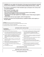
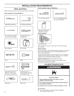
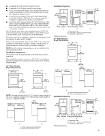
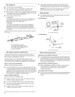
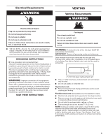
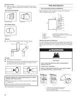
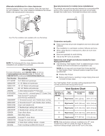
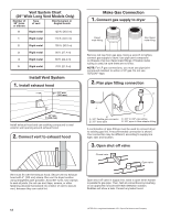
Gas supply line ■■ 1/2" NPT pipe is recommended. ■■ 3/8" approved tubing is acceptable for lengths under 20 ft. (6.1 m) if local codes and gas supplier permit. ■■ Must include 1/8" NPT minimum plugged tapping accessible for test gauge connection, immediately upstream of the gas connection to the dryer (see illustration). ■■ Must include a shut-off valve: In the U.S.A.: An individual manual shut-off valve must be installed within six (6) feet (1.8 m) of the dryer in accordance with the National Fuel Gas Code, ANSI Z223.1. In Canada: An individual manual shut-off valve must be installed in accordance with the B149.1, Natural Gas and Propane Installation Code. It is recommended that an individual manual shut-off valve be installed within six (6) feet (1.8 m) of the dryer. The shut-off valve location should be easy to reach for opening and closing. E C A D ■■ If your dryer has been converted to use LP gas, 3/8" LP compatible copper tubing can be used. If the total length of the supply line is more than 20 ft. (6.1 m), use larger pipe. NOTE: Pipe joint compounds that resist the action of LP gas must be used. Do not use TEFLON®† tape. Dryer gas pipe ■■ The gas pipe that comes out through the rear of your dryer has a 3/8" male pipe thread. 29" Wide Model 1¼" (32 mm) A 9¼" (235 mm) A. 3/8" NPT dryer pipe 27" Wide Model *5 3/4" A (146 mm) B A. 3/8" flexible gas connector B. 3/8" pipe to flare adapter fitting C. 1/8" NPT minimum plugged tapping D. 1/2" NPT gas supply line E. Gas shut-off valve Gas supply connection requirements There are many methods by which your gas dryer can be connected to the gas supply. Listed here are some guidelines for two different methods of connection. This dryer must be connected to the gas supply line with a listed flexible gas connector that complies with the standard for connectors for gas appliances, ANSI Z21.24 or CSA 6.10. Option 1 (Recommended Method) Flexible stainless steel gas connector: ■■ If local codes permit, use a new flexible stainless steel gas connector (Design Certified by the American Gas Association or CSA International) to connect your dryer to the rigid gas supply line. Use an elbow and a 3/8" flare x 3/8" NPT adapter fitting between the stainless steel gas connector and the dryer gas pipe, as needed to prevent kinking. Option 2 (Alternate Method) Approved aluminum or copper tubing: ■■ Lengths over 20 ft. (6.1 m) can use 3/8" approved tubing (if codes and gas supplier permit). ■■ If you are using Natural Gas, do not use copper tubing. ■■ 3/8" flare x 3/8" NPT adapter fitting between dryer pipe and 3/8" approved tubing. ■■ Lengths over 20 ft. (6.1 m) should use larger tubing and a different size adapter fitting. 11/2" (38 mm) A.A3./83"/8N" PNTPdTrdyeryr eprippeipe Burner input requirements Elevations up to 10,000 ft. (3,048 m): ■■ The design of this dryer is certified by CSA International for use at altitudes up to 10,000 ft. (3,048 m) above sea level at the B.T.U. rating indicated on the model/serial number plate. Burner input adjustments are not required when the dryer is operated up to this elevation. Elevations above 10,000 ft. (3,048 m): ■■ When installed above 10,000 ft. (3,048 m), a 4% reduction of the burner B.T.U. rating shown on the model/serial number plate is required for each 1,000 ft. (305 m) increase in elevation. Gas supply pressure testing ■■ The dryer must be disconnected from the gas supply piping system during pressure testing at pressures greater than 1/2 psi. †®TEFLON is a registered trademark of E.I. Du Pont De Nemours and Company. 8
-
 1
1 -
2
-
 3
3 -
 4
4 -
 5
5 -
 6
6 -
 7
7 -
 8
8 -
 9
9 -
 10
10 -
 11
11 -
 12
12 -
 13
13 -
14
-
15
-
16
-
17
-
18
-
19
-
20
-
21
-
22
-
23
-
24
-
25
-
26
-
27
-
28
-
29
-
30
-
31
-
32
-
33
-
34
-
35
-
36
-
37
-
38
-
39
-
40
-
41
-
42
-
43
-
44
 |
 |