Whirlpool WGD4985EW Installation Guide - Page 12
Install Vent System, Make Gas Connection
 |
View all Whirlpool WGD4985EW manuals
Add to My Manuals
Save this manual to your list of manuals |
Page 12 highlights
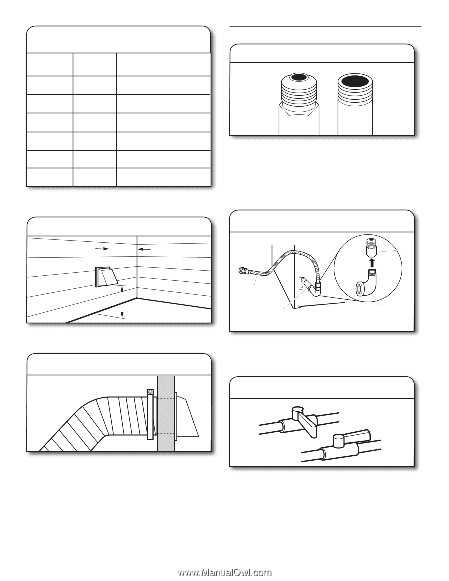
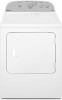
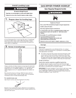
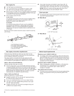
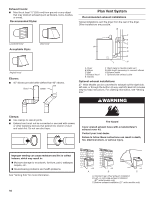
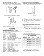
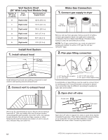
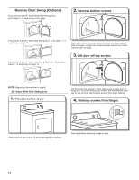
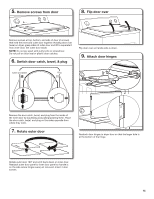
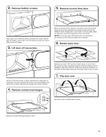
Vent System Chart (29" Wide Long Vent Models Only) Number of 90° turns or elbows Type of vent Box/louvered, or Angled hoods 0 Rigid metal 120 ft. (36.6 m) 1 Rigid metal 110 ft. (33.5 m) 2 Rigid metal 100 ft. (30.5 m) 3 Rigid metal 90 ft. (27.4 m) 4 Rigid metal 80 ft. (24.4 m) 5 Rigid metal 70 ft. (21.3 m) Install Vent System 1. Install exhaust hood 12" min. (305 mm) Make Gas Connection 1. Connect gas supply to dryer Flared maAle fitting mNoalne-fflBiattriendg Remove red cap from gas pipe. Using a wrench to tighten, connect gas supply to dryer. Use pipe-joint compound on threads of all non-flared male fittings. If flexible metal tubing is used, be sure there are no kinks. NOTE: For LP gas connections, you must use pipe-joint compound resistant to action of LP gas. Do not use TEFLON®† tape. 2. Plan pipe fitting connection D 12" min. (305 mm) Install exhaust hood and use caulking compound to seal exterior wall opening around exhaust hood. 2. Connect vent to exhaust hood A B A. 3/8" flexible gas connector B. 3/8" dryer pipe C C. 3/8" to 3/8" pipe elbow D. 3/8" pipe-to-flare adapter fitting A combination of pipe fittings must be used to connect dryer to existing gas line. A recommended connection is shown. Your connection may be different, according to supply line type, size, and location. 3. Open shut-off valve Closed Avalve OpBen valve Vent must fit over the exhaust hood. Secure vent to exhaust hood with 4" (102 mm) clamp. Run vent to dryer location using straightest path possible. Avoid 90° turns. Use clamps to seal all joints. Do not use duct tape, screws, or other fastening devices that extend into interior of vent to secure vent, because they can catch lint. Open shut-off valve in supply line; valve is open when handle is parallel to gas pipe. Then, test all connections by brushing on an approved noncorrosive leak-detection solution. Bubbles will show a leak. Correct any leaks found. 12 †®TEFLON is a registered trademark of E.I. Dupont De Nemours and Company.
-
 1
1 -
2
-
3
-
4
-
5
-
6
-
 7
7 -
 8
8 -
 9
9 -
 10
10 -
 11
11 -
 12
12 -
 13
13 -
 14
14 -
 15
15 -
 16
16 -
 17
17 -
18
-
19
-
20
-
21
-
22
-
23
-
24
-
25
-
26
-
27
-
28
-
29
-
30
-
31
-
32
-
33
-
34
-
35
-
36
-
37
-
38
-
39
-
40
-
41
-
42
-
43
-
44
 |
 |