Whirlpool WGE755C0BH Installation Guide - Page 12
Verify Anti-Tip Bracket Is Installed and, Engaged, Level Range
 |
View all Whirlpool WGE755C0BH manuals
Add to My Manuals
Save this manual to your list of manuals |
Page 12 highlights
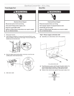
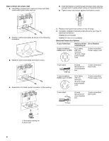
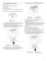
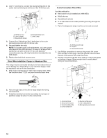
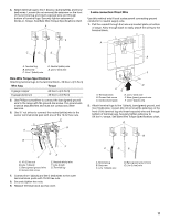
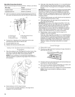
Bare Wire Torque Specifications Attaching terminal lugs to the terminal block - 20 lbs-in. (2.3 N-m) Wire Awg Torque 8 gauge copper 25 lbs-in. (2.8 N-m) 6 gauge aluminum 35 lbs-in. (4.0 N-m) 3. Use ³⁄₈" nut driver to connect the bare (green) ground wire to the center terminal block post with one of the 10-32 hex nuts. F A E B A. 10-32 hex nut B. Line 1 (black) C. Ground-link screw D C D. Bare (green) ground wire E. Line 2 (red) F. Terminal lug 4. Connect line 1 (black) and line 2 (red) wires to the outer terminal block posts with 10-32 hex nuts. 5. Securely tighten hex nuts. 6. Replace terminal block access cover. Verify Anti-Tip Bracket Is Installed and Engaged 1. Place the outside of your foot against the bottom front of the oven door to keep the range from moving, and grasp the lower right or left side of the control panel as shown. NOTE: If your countertop is mounted with a backsplash, it may be necessary to grasp the range higher than is shown in the illustration. 3. If the rear of the range lifts more than ½" (1.3 cm) off the floor without resistance, stop tilting the range and lower it gently back to the floor. The range foot is not engaged in the anti-tip bracket. IMPORTANT: If there is a snapping or popping sound when lifting the range, the range may not be fully engaged in the bracket. Check to see if there are obstructions keeping the range from sliding to the wall or keeping the range foot from sliding into the bracket. Verify that the bracket is held securely in place by the mounting screws. 4. Slide the range forward, and verify that the anti-tip bracket is securely attached to the floor or wall. 5. Slide range back so the rear range foot is inserted into the slot of the anti-tip bracket. IMPORTANT: If the back of the range is more than 2" (5.1 cm) from the mounting wall, the rear range foot may not engage the bracket. Slide the range forward and determine if there is an obstruction between the range and the mounting wall. If you need assistance or service, refer to the "Assistance or Service" section of the Use and Care Guide, or the cover or "Warranty" section of the User Instructions, for contact information. 6. Repeat steps 1 and 2 to ensure that the range foot is engaged in the anti-tip bracket. If the rear of the range lifts more than ½" (1.3 cm) off the floor without resistance, the anti-tip bracket may not be installed correctly. Do not operate the range without anti-tip bracket installed and engaged. Please reference the "Assistance or Service" section of the Use and Care Guide, or the cover or "Warranty" section of the User Instructions, to contact service. Level Range 1. Place a rack in oven. 2. Place level on rack and check levelness of range, first side to side; then front to back. 3. If range is not level, pull range forward until rear leveling leg is removed from the anti-tip bracket. 4. Use a wrench or pliers to adjust leveling legs up or down until the range is level. Push range back into position. 5. Check that rear leveling leg is engaged in the anti-tip bracket. NOTE: Range must be level for satisfactory baking performance. 2. Slowly attempt to tilt the range forward. If you encounter immediate resistance, the range foot is engaged in the anti-tip bracket. 12
-
 1
1 -
2
-
3
-
4
-
5
-
6
-
 7
7 -
 8
8 -
 9
9 -
 10
10 -
 11
11 -
 12
12 -
 13
13 -
 14
14 -
 15
15 -
 16
16 -
 17
17 -
18
-
19
-
20
-
21
-
22
-
23
-
24
 |
 |
