Whirlpool WMH32519H Installation Instructions - Page 3
Remove Cardboard Template, Location Requirements
 |
View all Whirlpool WMH32519H manuals
Add to My Manuals
Save this manual to your list of manuals |
Page 3 highlights
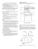
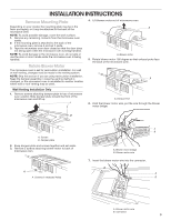
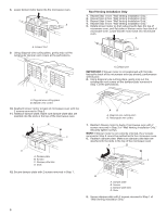
Remove Cardboard Template The cardboard piece from the top of the microwave oven packaging is perforated. The piece inside the perforation is for use as a rear wall template. 1. Cut along the perforation to separate the template from the rest of the cardboard packaging. 2. Set the cardboard template to the side and refer to it during the "Mark Rear Wall" part of installation. Depending on your model, skip "Remove Cardboard Template" steps if full carton box is used for packing. But use the wall template for "Mark Rear Wall" part of the installation. Location Requirements Check the opening where the microwave oven will be installed. The location must provide: ■■ Minimum installation dimensions. See the "Installation Dimensions" illustration. ■■ Minimum one 2" x 4" (5.1 x 10.2 cm) wood wall stud and minimum 3/8" (1 cm) thickness drywall or plaster/lath within cabinet opening. ■■ Support for weight of 150 lbs (68 kg) which includes microwave oven and items placed inside the microwave oven and upper cabinet. ■■ Grounded electrical outlet inside upper cabinet. See the "Electrical Requirements" section. NOTES: ■■ If installing the microwave oven near a left sidewall, make sure there is at least 6" (15.2 cm) of clearance between the wall and the microwave oven so that the door can open fully. ■■ Some models have a pocket handle. If installing the microwave near a right side wall, make sure there is at least 3 inches of clearance between wall and microwave oven so you can grab the handle integrated inside the door. ■■ Some cabinet and building materials are not designed to withstand the heat produced by the microwave oven for cooking. Check with your builder or cabinet supplier to make sure that the materials used will not discolor , delaminate, or sustain other damages. Special Requirements For Wall Venting Installation Only: ■■ Cutout must be free of any obstructions so that the vent fit properly and the damper blade opens freely and fully. For Roof Venting Installation Only: ■■ If you are using a rectangular-to-round transition piece, the 3" (7.6 cm) clearance needs to exist above the microwave oven so that the damper blade can open freely and fully. See "Rectangular to Round Transition" illustration in the "Venting Design Specifications" section. Installation Dimensions NOTE: The grounded 3 prong outlet must be inside the upper cabinet. See the "Electrical Requirements" section. A B 66" (167.6 cm) min. 30" (76.2 cm) min. 30" (76.2 cm) typical* 12" (30.5 cm) min. 14" (35.6 cm) max. upper cabinet and side cabinet depth A. 2" x 4" (5.1 x 10.2 cm) wall stud B. Grounded 3 prong outlet *30" (76.2 cm) is typical for 66" (167.6 cm) installation height. Exact dimensions may vary depending on type of range/cooktop below. NOTE: To ensure good performance, do not obstruct top vent airflow. If cabinets are deeper than 14" (35.6 cm) but no more than 15" (38.1 cm), use the bump out mounting kit replacing the I bar mounting plate fr om the wall. The bump out mounting kit (part # W11185746) is not provided but can be purchased from Whirlpool. 12" DEEPER 14" 14" DEEPER 15" I bar mounting plate Bump out mounting bracket Product Dimensions 17¹⁄₈" (43.5 cm 0.5 cm) 16¹⁄₄" (41.3 cm) (42.15U6c³p⁄m₄t"o)* 29⁷⁄₈" (76.0 cm) *Overall depth of product will vary slightly depending on door design. 3
-
 1
1 -
 2
2 -
 3
3 -
 4
4 -
 5
5 -
 6
6 -
 7
7 -
 8
8 -
 9
9 -
10
-
11
-
12
-
13
-
14
-
15
-
16
-
17
-
18
-
19
-
20
-
21
-
22
-
23
-
24
-
25
-
26
-
27
-
28
 |
 |
