Whirlpool WOEC5030LZ Owners Manual - Page 15
Install Deflector Kit, Parts Supplied in Deflector Kit
 |
View all Whirlpool WOEC5030LZ manuals
Add to My Manuals
Save this manual to your list of manuals |
Page 15 highlights
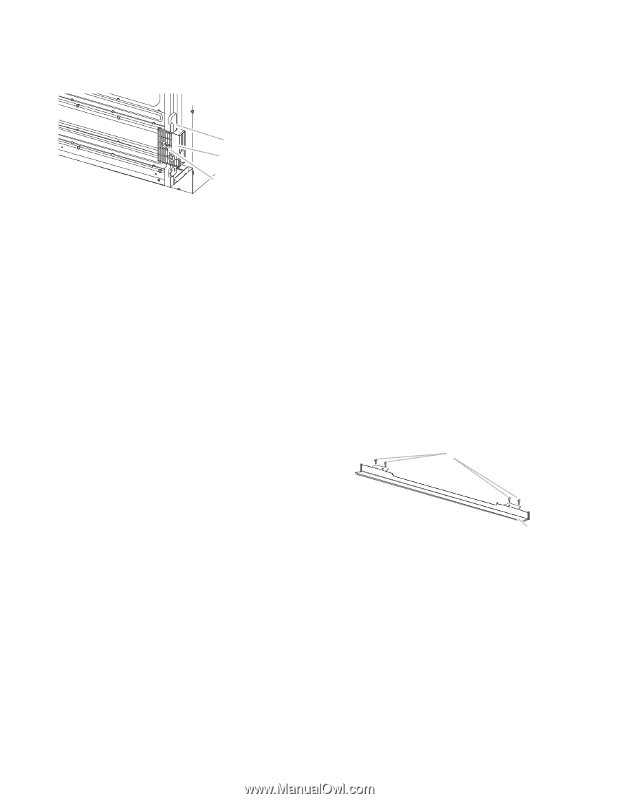
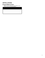
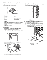
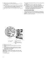
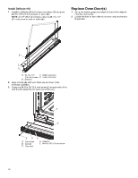
2. Install a foot on the left rear spacer using a #8-18 x 3/8" (9.5 mm) screw. NOTE: Position the foot so the long side of the foot is facing toward the top of the oven. 6. Using 2 or more people, place the oven in its upright position. A B C A. Spacers B. Foot C. #8-18 x 3/8" (9.5 mm) screw. 3. In the same manner, install a foot on the right rear of the oven. 4. Install a front foot on the left front spacer using a #8-18 x 3/8" (9.5 mm). NOTE: Position the foot so the long side of the foot is facing toward the inside of the oven. 7. Go to the "Make Electrical Connection" section in the Installation Instructions provided with your built-in oven. Install Deflector Kit On single and double oven models installed above a warming drawer or for ovens installed using flush installation cabinetry, a deflector kit must be installed. See the "Tools and Parts" section for information on ordering. Parts Supplied in Deflector Kit A A. Front foot B. #8-18 x 3/8" (9.5 mm) screw. C. Spacer 5. In the same manner, install a front foot on the right front of the oven. B A. Phillips head screws (4), only 2 screws for 27" (68.6 cm) size B. Deflector (1) 15
-
 1
1 -
2
-
3
-
4
-
5
-
6
-
7
-
8
-
9
-
 10
10 -
 11
11 -
 12
12 -
 13
13 -
 14
14 -
 15
15 -
 16
16 -
 17
17 -
 18
18 -
 19
19 -
 20
20 -
21
-
22
-
23
-
24
-
25
-
26
-
27
-
28
-
29
-
30
-
31
-
32
-
33
-
34
-
35
-
36
-
37
-
38
-
39
-
40
-
41
-
42
-
43
-
44
-
45
-
46
-
47
-
48
-
49
-
50
-
51
-
52
-
53
-
54
-
55
-
56
 |
 |