Whirlpool WSR57R18D Instruction Sheet - Page 1
Whirlpool WSR57R18D Manual
 |
View all Whirlpool WSR57R18D manuals
Add to My Manuals
Save this manual to your list of manuals |
Page 1 highlights
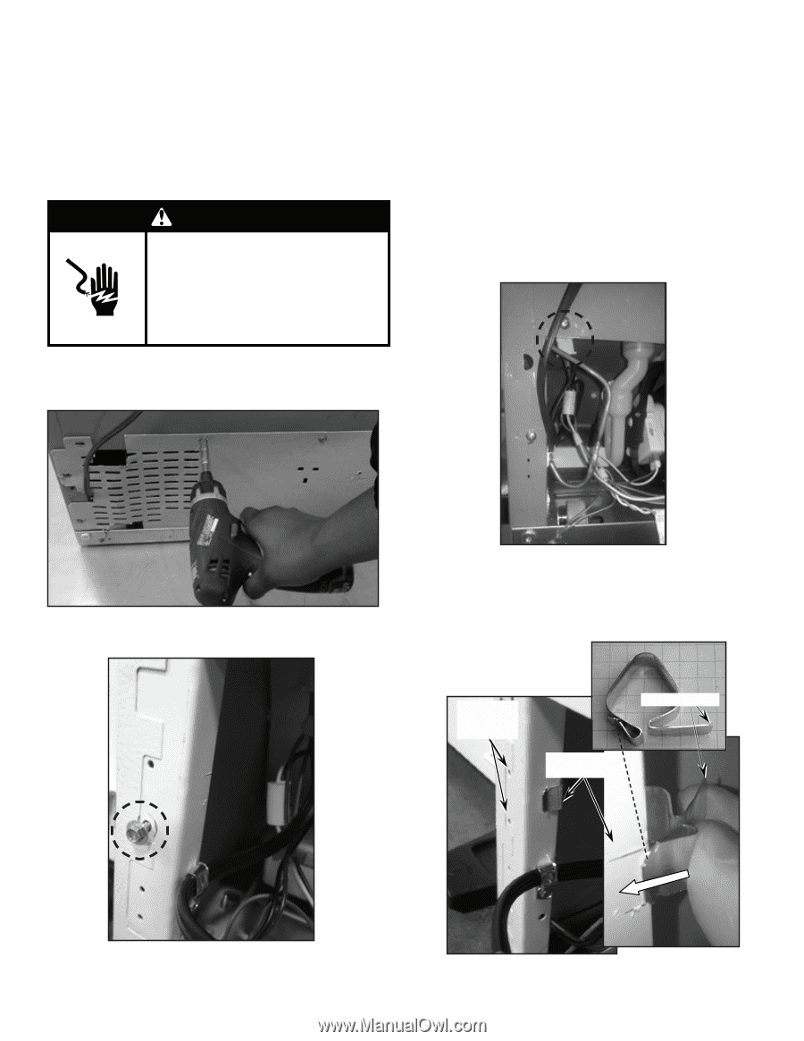
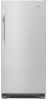
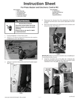
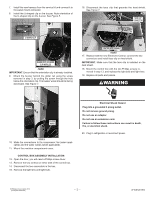
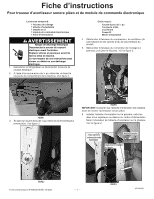
Instruction Sheet For Piezo Buzzer and Electronic Control Kit Kit Contains: 1 Wire Harness 1 Orientation Clip 1 U-shaped Clip 1 Electronic Control 1 Instruction Sheet Tools Needed: ¼" Nut Driver Phillips Screwdriver Wire Cutter Inspection Mirror WARNING Electrical Shock Hazard Disconnect power before servicing. Replace all parts and panels before operating. Failure to do so can result in death or electrical shock. 4. Disconnect the harness from the compressor, fan (when applicable) and the water valves (when applicable) from the product. 5. Disconnect the harness from the panel mount connector and discard harness. See Figure 3. 1. Unplug refrigerator or disconnect power. 2. Using a ¼" nut driver remove the screws from the machine compartment cover. See Figure 1. figure 1 3. Using a ¼" nut driver remove the screw from the piezo buzzer. See Figure 2. figure 3 IMPORTANT: Make sure that the orientation clip is installed prior to mounting the piezo buzzer. 6. Install the orientation clip on the glider rail, in between the top two holes above the power cord. Note orientation of the orientation clip on the glider rail. See Figure 4. top 2 holes above power cord Orientation clip clip installation location figure 2 Instruction Sheet W10812019 Rev. B 8/24 - 1 - figure 4 (continued)
-
 1
1 -
 2
2 -
 3
3 -
 4
4 -
 5
5 -
 6
6
 |
 |