Whirlpool WSR57R18D Instruction Sheet - Page 2
Warning
 |
View all Whirlpool WSR57R18D manuals
Add to My Manuals
Save this manual to your list of manuals |
Page 2 highlights
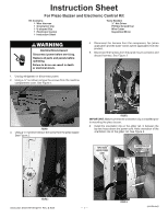
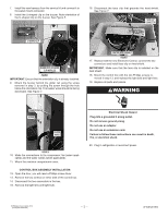
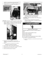
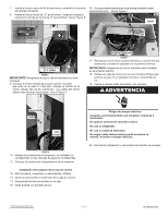
7. Install the new harness from the service kit and connect it to the panel mount connector. 8. Install the U-shaped clip on the buzzer. Note orientation of the U-shaped clip on the buzzer. See Figure 5. 16. Disconnect the taco clip that grounds the heat shield. See Figure 7. taco clip connector U-shaped clip buzzer with u-shaped clip installed figure 5 IMPORTANT: Ensure that the orientation clip is already installed. 9. Mount the buzzer behind the glider rail using the screw removed in step 3, by putting the screw through the hole below the orientation clip. The buzzer wires should be facing downward. See Figure 7. control box assembly figure 7 17. Replace with the new Electronic Control, connect the two connectors and install taco clip on heat shield. IMPORTANT: Make sure that the taco clip is installed on the heat shield. 18. Mount the control box with the two Phillips screws re- moved in step 13, and replace the light bulb and light lens. 19. Replace all parts and panels. WARNING Orientation clip screw buzzer wires figure 6 10. Make the connections to the compressor, fan (when appli- cable) and the water valves (when applicable). 11. Mount the machine compartment cover. Control Box assembly installation 12. Open the door; you will need a Phillips screw driver. 13. Remove the two screws on either side of the control box. 14. Disconnect the two connectors in the box. 15. Remove the light lens and light bulb. Electrical Shock Hazard Plug into a grounded 3 prong outlet. Do not remove ground prong. Do not use an adapter. Do not use an extension cord. Failure to follow these instructions can result in death, fire, or electrical shock. 20. Plug in refrigerator or reconnect power. © Whirlpool Corporation 2014 ( All Rights Reserved) - 2 - W10812019 B
-
 1
1 -
 2
2 -
 3
3 -
 4
4 -
 5
5 -
 6
6
 |
 |
