Yamaha Audiogram3 Owners Manual - Page 19
Input Signal Flow, Rear Panel
 |
View all Yamaha Audiogram3 manuals
Add to My Manuals
Save this manual to your list of manuals |
Page 19 highlights
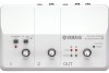
Rear Panel Controls and Functions !1 !0 8 MIC/INST Input Jack Microphones and instruments such as guitars can be connected here using XLR or phone jack cables. Set the MIC/INST switch 2 to MIC or INST according to the type of device connected. XLR-type Phone-type o i If devices are connected to both phone and pin jacks, only the signal from the device connected to the phone jacks is input. Phone-type Pin-type NOTE You can directly connect an electric guitar or bass without the need for a separate DI (Direct Injection) box or amp simulator. 9 LINE Input Jacks These inputs are intended mainly for use with instruments and equipment having stereo outputs, such as a synthesizer or CD player. ■ Input Signal Flow Adjust the recording level as well as the balance between channels. 0 STEREO OUT Jacks These output the mixed signal from channels 1 and 2. The output level can be adjusted using the OUT LEVEL control. These jacks would typically be connected to an audio system (monitor speakers). NOTE You can use either the phone jacks or pin jacks but not both at the same time. If both jacks are used, the signal is only output from the phone jacks. A PHONES Jack Connects a pair of headphones to this jack. The PHONES jack outputs the same signal as the STEREO OUT jacks. 5 Level indicator Adjusts the monitor level. Input 3 LEVEL Record controls Playback 6 OUT LEVEL control Cubase AI Output AUDIOGRAM 3 Owner's Manual 19
-
 1
1 -
2
-
3
-
4
-
5
-
6
-
7
-
8
-
9
-
10
-
11
-
12
-
13
-
 14
14 -
 15
15 -
 16
16 -
 17
17 -
 18
18 -
 19
19 -
 20
20 -
 21
21 -
 22
22 -
 23
23 -
 24
24 -
25
-
26
 |
 |
