Yamaha DTX482K DTX482K Owners Manual - Page 1
Yamaha DTX482K Manual
 |
View all Yamaha DTX482K manuals
Add to My Manuals
Save this manual to your list of manuals |
Page 1 highlights
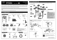
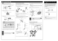
ELECTRONIC DRUM KIT DTX482K Owner's Manual EN Manual Development Group © 2018 Yamaha Corporation Published 08/2014 POMA*.*-**A0 VAU5550 Thank you for purchasing the Yamaha DTX482K! As a high-end model of the DTX402 series, the DTX482K comes standard with three cymbal pads (two crashes and one ride) and the DTX-series XP80 Snare Pad. We recommend that you read this manual carefully so that you can fully take advantage of the advanced and convenient functions of the instrument. We also recommend that you keep this manual in a safe and handy place for future reference. Before using this product, be sure to read the "PRECAUTIONS" on pages 4 to 5 on the DTX402K, DTX432K, and DTX452K Owner's Manual. NOTICE Some objects made of rubber and similar materials can easily stain the drumhead of the snare pad. Do not leave such objects in contact with the drumhead for a long period of time. Pay special attention to avoid stacking the pads when putting them in storage, for example. 1. Package Content After opening up the package containing your electronic drum kit, please verify that all of the following parts are present. DTX482K Package Content Rack (Large) Rack (Small) Rod for the snare pad Hi-hat holder Stopper Cymbal holders (×2) No Stopper Pipe for TOM3 Drum module KP65 Kick pad Cymbal/hi-hat pads (×2) Crash cymbal pad HH65 Hi-hat controller FP6110A Foot pedal 2. Assembly Guide (1/2) To assemble the DTX482K, refer to this Owner's Manual and the DTX402K, DTX432K, and DTX452K Owner's Manual Fully Assembled DTX482K Step 10 Step 8 Step 9 Step 5 Step 9 Step 7 Step 6 Step 4 Step 2 Step 3 Step 12 Step 11 Step 12 Additional cymbal pad Cable band position Step 1 CAUTION • Choose a flat, hard surface on which to assemble your electronic drum kit. • Take care to avoid mixing up parts or assembling them in the wrong direction. In addition, the assembly steps should be completed one at a time in the order described. • The assistance of at least one other person will be required when assembling the electronic drum kit. • Once a piece has been assembled, be sure to tighten the corresponding key bolts. • To disassemble your electronic drum kit, carry out the assembly sequence in reverse. Attaching the cymbal holder for the additional cymbal pad. 1. Loosen the (1, 2) key bolts and detach the pipe for TOM3. w r 2 Pipe for TOM3 3. Slide the holder clamp onto the TOM3 pipe, and lightly tighten the clamp bolt of the cymbal holder. Holder clamp Clamp bolt Nine-channel snake cable Drum key Sensor (bumps) Cable bands (×3) Additional Cymbal pad Cymbal pad (×1) Cymbal holder (×1) Stopper (×1) AC adaptor * May not be included depending on your particular area. Please check you're your Yamaha dealer. DTX482K Owner's Manual (this booklet) DTX402K, DTX432K, and DTX452K Owner's Manual KP65 Owner's Manual XP70, XP80 Owner's Manual XP80 Snare Pad XP80 main unit (×1) Clamp bolt (×1) Stereo audio cable (×1) e q 1 2. Loosen the clamp bolt of the cymbal holder. Clamp bolt Cymbal holder 1 4. Attach the TOM3 pipe back to the large rack. Pipe for TOM3 5. Tighten the key bolt ( in the above figure) on the large rack and the clamp bolt of the cymbal holder. Step 1 Step 2 Step 3 Turn the entire large rack over and continue with the assembly by following the instructions on pages 13 and 14 of the DTX402K, DTX432K, and DTX452K Owner's Manual Continue to the other side.
-
 1
1 -
 2
2
 |
 |