Yamaha EMX640 Owner's Manual - Page 5
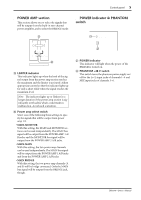
POWER AMP POWER indicator & PHANTOM, switch
 |
View all Yamaha EMX640 manuals
Add to My Manuals
Save this manual to your list of manuals |
Page 5 highlights
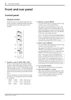
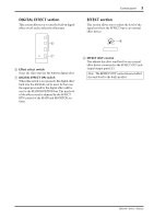
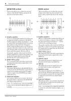
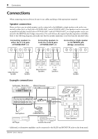
Control panel 5 s POWER AMP section This section allows you to select the signals that will be output from the built-in two-channel power amplifier, and to select the BRIDGE mode. I 1 2 LIMITER MAIN BRIDGE MAIN MAIN MAIN MONITOR J POWER AMP I LIMITER indicator This indicator lights up when the level of the signal output from the power amp section reaches the maximum and the limiter is activated. Adjust appropriate control so that the indicator lights up for only a short while when the signal reaches the maximum level. Note: The indicator lights up or flashes for a longer duration if the power amp section is significantly overloaded, which could result in malfunction. Avoid such a situation. J Power amp select switch Select one of the following three settings to specify the signals that will be output from power amp 1/2. • MAIN-MONITOR With this setting, the MAIN and MONITOR sections can be used independently. The MAIN bus signal will be output from the POWER AMP 1 A/ B jacks, and the MONITOR bus signal will be output from the POWER AMP 2 A/B jacks. • MAIN-MAIN With this setting, the two power amp channels can be used independently. The MAIN bus signal will be output from the POWER AMP 1 A/B jacks and from the POWER AMP 2 A/B jacks. • MAIN BRIDGE With this setting, the two power amp channels (A and B) will be bridge connected. Only the MAIN bus signal will be output from the BRIDGE jack, though. s POWER indicator & PHANTOM switch K POWER ON OFF PHANTOM +48V L K POWER indicator This indicator will light when the power of the EMX640 is turned on. L PHANTOM +48 V switch This switch turns the phantom power supply on/ off for the Lo-Z input jacks of channels 1~4 and MIC input jacks of channels 5~6. EMX640-Owner's Manual
-
 1
1 -
 2
2 -
 3
3 -
 4
4 -
 5
5 -
 6
6 -
 7
7 -
 8
8 -
 9
9 -
 10
10 -
 11
11 -
12
-
13
-
14
-
15
-
16
 |
 |