Yamaha EMX640 Owner's Manual - Page 8
Connections - diagram
 |
View all Yamaha EMX640 manuals
Add to My Manuals
Save this manual to your list of manuals |
Page 8 highlights
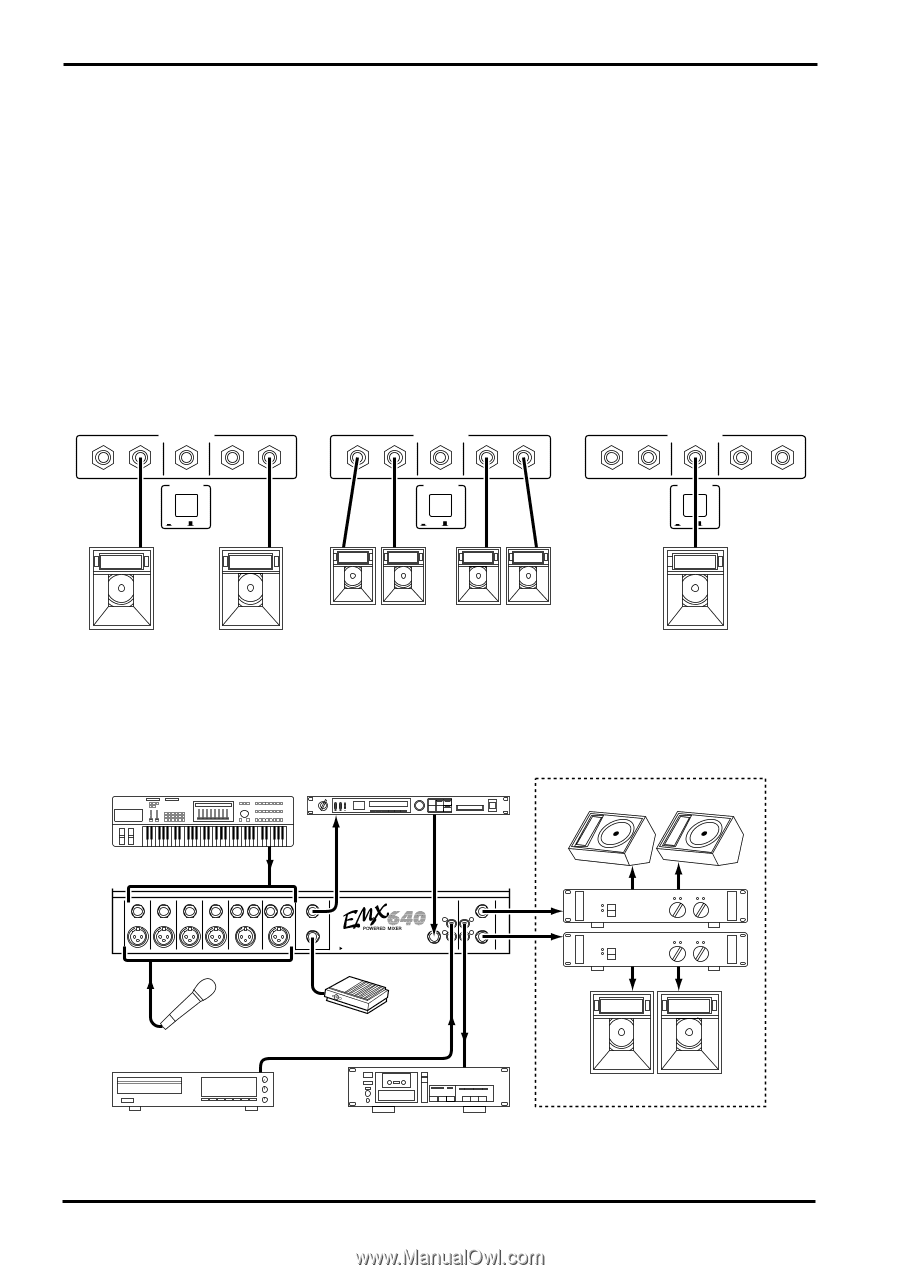
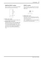
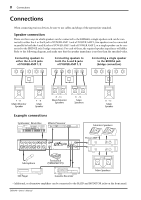
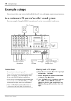
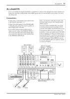
8 Connections Connections When connecting various devices, be sure to use cables and plugs of the appropriate standard. s Speaker connection There are three ways in which speakers can be connected to the EMX640; a single speaker each can be connected to either the A or the B jack of POWER AMP 1 and of POWER AMP 2, two speakers can be connected in parallel to both the A and B jacks of POWER AMP 1 and of POWER AMP 2, or a single speaker can be connected to the BRIDGE jack (bridge connection). For each of these, the required speaker impedance will differ. Refer to the following diagram, and make sure that the speaker impedance is not less than the specified value. Connecting speakers to either the A or B jacks of POWER AMP 1/2 SPEAKERS B A B A POWER AMP 2 BRIDGE POWER POWER AMP 1 Connecting speakers to both the A and B jacks of POWER AMP 1/2 SPEAKERS B A B A POWER AMP 2 BRIDGE POWER POWER AMP 1 Connecting a single speaker to the BRIDGE jack (bridge connection) SPEAKERS B A B A POWER AMP 2 BRIDGE POWER POWER AMP 1 ON / OFF ON / OFF ON / OFF 4Ω~8Ω Main/Monitor Speaker 4Ω~8Ω Main Speaker 8Ω~16Ω Main/Monitor Speakers s Example connections Synthesizer, Drum Box Effects Processor 88 8Ω~16Ω Main Speakers 8Ω~16Ω Main Speaker Monitors Speakers Hi-Z Hi-Z Hi-Z Hi-Z 1 LINE 2 1 LINE 2 EFFECT OUT Lo-Z Lo-Z Lo-Z Lo-Z MIC MIC FOOT SW SEE REAR PANEL CAUTION MONITOR TAPE REC IN OUT AUX IN MAIN INPUT TO MAIN OUTPUT Power AMP Microphone Footswitch (YAMAHA FC5) CD Player Cassette Recorder Main Speakers • Additional, or alternative amplifiers can be connected to the MAIN and MONITOR jacks on the front panel. EMX640-Owner's Manual
-
 1
1 -
2
-
 3
3 -
 4
4 -
 5
5 -
 6
6 -
 7
7 -
 8
8 -
 9
9 -
 10
10 -
 11
11 -
 12
12 -
 13
13 -
14
-
15
-
16
 |
 |