Yamaha MDX-E300 Owner's Manual - Page 9
Connecting RX-E400 and CDX-E400, GETTING STARTED
 |
View all Yamaha MDX-E300 manuals
Add to My Manuals
Save this manual to your list of manuals |
Page 9 highlights
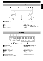
English Connecting RX-E400 and CDX-E400 Receiver (RX-E400) Audio pin cables (included) C IN MD OUT D A IN TAPE OUT B IN CD E IN AUX R FM ANT 75Ω UNBAL. GND AM ANT L R L + - SUBWOOFER SYSTEM OUT CONNECTOR 6Ω MIN./SPEAKER SPEAKERS CD player (CDX-E400) GETTING STARTED To wall outlet System control cable To RX-E400 ANALOG E OUT L DIGITAL OPTICAL SYSTEM CONNECTOR OUT R This unit (MDX-E300) Optical cable (included) System control cable (included) To RX-E400 ANALOG SYSTEM IN D L C OUT CONNECTOR 1 DIGITAL OPTICAL 2 OUT IN R Notes • The ANALOG OUT jacks on this unit are marked Ç and the ANALOG IN jacks are marked Î. When connecting this unit to RX-E400 whose jacks are marked and ‰, connect this unit's ANALOG OUT jacks to the input jacks marked Ç and connect this unit's ANALOG IN jacks to the output jacks marked Î on the rear panel of RX-E400. • The SYSTEM CONNECTOR jack should be connected to the SYSTEM CONNECTOR jack on CDX-E400. • For digital recording, the DIGITAL OPTICAL 1 IN jack should be connected to the DIGITAL OPTICAL OUT jack on CDX-E400. 7
-
 1
1 -
2
-
3
-
 4
4 -
 5
5 -
 6
6 -
 7
7 -
 8
8 -
 9
9 -
 10
10 -
 11
11 -
 12
12 -
 13
13 -
 14
14 -
15
-
16
-
17
-
18
-
19
-
20
-
21
-
22
-
23
-
24
-
25
-
26
-
27
-
28
 |
 |
