Yamaha MG12XU Owner's Manual - Page 19
ON] switches, PEAK] indicators, Bus assign switch, PFL] Pre-fader Listen switch, Channel faders
 |
View all Yamaha MG12XU manuals
Add to My Manuals
Save this manual to your list of manuals |
Page 19 highlights
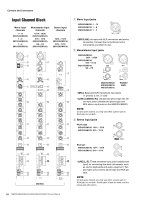
Controls and Connectors • BAL: Sets the volume balance of the signal sent from each stereo input channel (L/R) to the STEREO L/R bus or GROUP bus. When this knob is set to the 12 o'clock position, the sound of the stereo input channels (L/R) will be sent to the STEREO L/R bus or GROUP 1, 3/2, 4 bus at the same volume. BAL LINE L LINE R STEREO L bus, GROUP 1 bus, GROUP 3 bus STEREO R bus, GROUP 2 bus, GROUP 4 bus • PAN/BAL: This knob performs both [PAN] and [BAL] functions. You can use this as a [PAN] control when sound is input to the [LINE] (L/MONO) jack, and as a [BAL] control when sound is input to both the [LINE] (L) and [LINE] (R) jacks. !3 [ON] switches Turn this switch on ( ) to send the respective channel's signal to the buses. The switch lights when on. When this switch is off ( ), the respective signal input is not sent to the AUX bus or GROUP bus. NOTE • Even if the [ON] switch is off, the PFL signal from each channel can still be monitored via the [PHONES] jack. • To minimize noise, turn the [ON] switch off for any unused channels. !4 [PEAK] indicators These switches determine the bus(es) to which each channel's signal is sent. Turn the switch on ( ) to output the signal to the corresponding buses. • [1-2] switch: Assigns the channel's signal to the GROUP 1-2 buses. • [3-4] switch: Assigns the channel's signal to the GROUP 3-4 buses. • [ST] switch: Assigns the channel's signal to the STE- REO L/R buses. NOTE To send the signal to each bus, engage the [ON] switch !3. !6 [PFL] (Pre-fader Listen) switch When the [PFL] switch is on ( ), the channel pre-fader signal is output to the [MONITOR OUT] and [PHONES] jacks for monitoring. In this condition, the audio from the STEREO L/R buses or GROUP buses that could be heard in the [MONITOR OUT] and [PHONES] jacks can no longer be heard. When a [PFL] switch is turned on, the [PFL] indicator below the level meter flashes. !7 Channel faders The peak level of the post-EQ signal is detected, and the PEAK indicator lights red when the level reaches 3 dB below clipping. !5 Bus assign switch For adjusting the level of the channel signal. Use these controls to adjust the balance between the various channels. NOTE To minimize noise, set the fader sliders for any unused channels all the way down. MG20XU/MG20 MG16XU/MG16 MG12XU/MG12 MG20XU/MG20/MG16XU/MG16/MG12XU/MG12 Owner's Manual 19
-
 1
1 -
2
-
3
-
4
-
5
-
6
-
7
-
8
-
9
-
10
-
11
-
12
-
13
-
 14
14 -
 15
15 -
 16
16 -
 17
17 -
 18
18 -
 19
19 -
 20
20 -
 21
21 -
 22
22 -
 23
23 -
 24
24 -
25
-
26
-
27
-
28
-
29
-
30
-
31
-
32
-
33
-
34
-
35
-
36
-
37
-
38
-
39
-
40
 |
 |
