Yamaha MG206C-USB Owner's Manual - Page 22
Level Meter, RETURN, Master SEND Controls AUX, EFFECT, MONITOR/PHONES, 2TR IN/USB, GROUP 1-2 Fader
 |
View all Yamaha MG206C-USB manuals
Add to My Manuals
Save this manual to your list of manuals |
Page 22 highlights
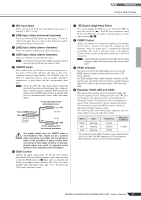
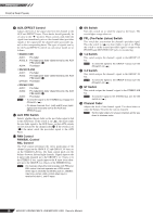
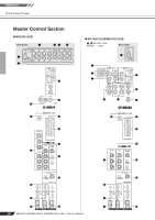
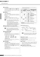
Reference Front & Rear Panels B Level Meter This LED meter displays the level of the signal selected by the MONITOR switch E, 2TR IN/USB switch F and PFL switch. The "0" segment corresponds to the nominal output level. The PEAK indicator lights red when the output reaches the clipping level. C RETURN • AUX1, AUX2 Control Adjusts the level at which the L/R signal received at the RETURN jacks (L (MONO) and R) is sent to the AUX1 and AUX2 buses. • STEREO Control Adjusts the level at which the signal received at the RETURN jacks (L (MONO) and R) is sent to the STEREO L/R bus. NOTE • If you supply a signal to the RETURN L (MONO) jack only, the mixer sends the same signal to both the L and R STEREO buses. • (MG206C-USB) Signals input via the RETURN1 jacks are adjusted using the RETURN1 AUX1, AUX2 and the STEREO controls, and signals input via the RETURN2 jacks are adjusted using the RETURN2 AUX1, AUX2 and the STEREO controls. D Master SEND Controls (AUX, EFFECT) Adjusts the signal level sent to the SEND (AUX, EFFECT) jacks. NOTE If you are using the MG166CX-USB, the Master SEND control (EFFECT) does not affect the level of the signal sent from the EFFECT bus to the internal digital effect processor. E MONITOR/PHONES • MONITOR switches These switches select the signal sent to the MONITOR OUT jacks, PHONES jack and the level meter from STEREO L/R bus, GROUP 1/2 bus or GROUP 3/4 bus. STEREO L/R bus: STEREO ( ) GROUP 1/2 bus: GROUP ( ), 1-2 ( ) GROUP 3/4 bus: GROUP ( ), 3-4 ( ) • MONITOR Control Controls the level of the signal output to the PHONES jack and the MONITOR OUT jacks. F 2TR IN/USB • 2TR IN/USB Switch If this switch is set to TO MONITOR ( ), the signals input via the 2TR IN jacks and the USB connector are sent to the MONITOR OUT jacks, the PHONES jack, and the level meter. If it is set to TO STEREO ( ), the signals are sent to the STEREO L/R bus. • 2TR IN/USB Control Adjusts the level of the signal sent from the 2TR IN jacks and the USB connector. The following illustration shows how the switch settings correspond to the signal selection. Switches Signals output via the PFL MONITOR/ PHONES 2TR IN/USB MONITOR/PHONES jacks ON - - PFL STEREO OFF 1-2 GROUP 3-4 TO STEREO STEREO (+ 2TR IN/USB) TO MONITOR STEREO + 2TR IN/USB * TO STEREO GROUP 1-2 TO MONITOR GROUP 1-2 (+ 2TR IN/USB) TO STEREO GROUP 3-4 TO MONITOR GROUP 3-4 (+ 2TR IN/USB) * : When overdubbing, you can adjust the levels of the mon- itor playback signal and the signal being recorded separately. MONITOR MIX Signal Flow 2TR IN/USB 2TR IN/USB control Playback signal Recording signal MONITOR/PHONES controls STEREO bus MONITOR OUT/PHONES jacks STEREO OUT Master fader REC OUT/USB jacks NOTE If the input channel PFL switch is on ( ), then only the PFL output from that channel is sent to the MONITOR OUT jacks, PHONES jack, and level meter. G GROUP 1-2 Fader Adjusts the signal level sent to the GROUP OUT 1/2 jacks. H GROUP 3-4 Fader Adjust the signal level to the GROUP OUT 3/ 4 jacks. I ST Switch If this switch is on, the signals are sent to the STEREO L/R bus via the GROUP 1-2 fader or GROUP 3-4 fader. The GROUP 1 and 3 signals go to STEREO L and the GROUP 2 and 4 signals go to STEREO R. J STEREO OUT Master Fader Adjusts the signal level sent to the STEREO OUT jacks. 22 MG206C-USB/MG166CX-USB/MG166C-USB Owner's Manual
-
 1
1 -
2
-
3
-
4
-
5
-
6
-
7
-
8
-
9
-
10
-
11
-
12
-
13
-
14
-
15
-
16
-
 17
17 -
 18
18 -
 19
19 -
 20
20 -
 21
21 -
 22
22 -
 23
23 -
 24
24 -
 25
25 -
 26
26 -
 27
27 -
28
-
29
-
30
-
31
-
32
-
33
-
34
-
35
-
36
-
37
 |
 |