Yamaha PM5D Pm5d Editor Owner's Manual - Page 23
COMPRESSOR, COMP LINK GROUP Compressor link group
 |
View all Yamaha PM5D manuals
Add to My Manuals
Save this manual to your list of manuals |
Page 23 highlights
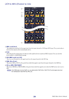
❏ COMPRESSOR 1 24 3 6 5 9 K J 8 7 M LN A Compressor graph Indicates the approximate response for the compressor of the currently selected channel. B GR meter This meter indicates the amount of gain reduction produced by the compressor. C TYPE Indicates the type of the currently selected compressor. D THRESHOLD (Threshold level) Specifies the threshold level at which the compressor will operate. The input signal will start being compressed when the key-in signal exceeds this level; compression will be removed when the signal falls below this level. E RATIO Specifies the ratio at which the input signal will be compressed when the key-in signal exceeds the threshold. F KNEE Specifies the sharpness at which the output level will change. You can select from HARD or 1-5. G ATTACK (Attack time) Specifies the time from when the key-in signal exceeds the threshold level until the signal starts being compressed. H RELEASE (Release time) Specifies the time from when the key-in signal falls below the threshold level until compression is removed. I GAIN Adjusts the gain of the signal after it has passed through the compressor. J ON (On/off) This button switches the compressor on/off. K LIBRARY This button accesses the compressor library. Clicking this button will open the COMP page of the LIBRARY window. L LINK (Stereo link) This button links the parameter settings and key-in signals of adjacent odd-numbered/even-numbered input channels or the L/R sides of a ST IN channel, so that compression will operate in tandem for the two channels. M COMP LINK GROUP (Compressor link group) Selects the compressor link group (1-8) to which that channel belongs. N KEY IN Selects the signal that will be used as the key-in signal. The types of signal that can be selected are the same as for the gate key-in signal (➥ p.22). 23 PM5D Editor Owner's Manual
-
 1
1 -
2
-
3
-
4
-
5
-
6
-
7
-
8
-
9
-
10
-
11
-
12
-
13
-
14
-
15
-
16
-
17
-
 18
18 -
 19
19 -
 20
20 -
 21
21 -
 22
22 -
 23
23 -
 24
24 -
 25
25 -
 26
26 -
 27
27 -
 28
28 -
29
-
30
-
31
-
32
-
33
-
34
-
35
-
36
-
37
-
38
-
39
-
40
-
41
-
42
-
43
-
44
-
45
-
46
-
47
-
48
-
49
-
50
-
51
-
52
-
53
-
54
-
55
-
56
-
57
-
58
-
59
-
60
-
61
-
62
-
63
-
64
-
65
 |
 |
