Yamaha RX-V440 MCXSP10 Manual - Page 20
IMPEDANCE SELECTOR switch, Connections, together to prevent short circuits.
 |
UPC - 027108916415
View all Yamaha RX-V440 manuals
Add to My Manuals
Save this manual to your list of manuals |
Page 20 highlights
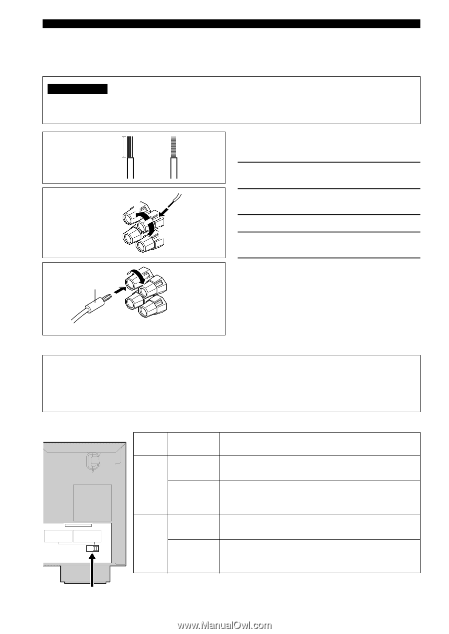
CONNECTIONS I Connections Be sure to connect the left channel (L), right channel (R), "+" (red) and "-" (black) in accordance with the markers on this unit, the speakers, and the speaker cables. If the connections are faulty, no sound will be heard from the speakers, and if the polarity of the speaker connections is incorrect, the sound will be unnatural and lack bass. CAUTION • Use speakers with the specified impedance shown on the rear panel of this unit. • Do not let the bare speaker wires touch each other or any metal part of this unit. This could damage this unit and/ or the speakers. 10 mm (3/8") A speaker cord is actually a pair of insulated cables running side by side. One cable is colored or shaped differently, perhaps with a stripe, groove or ridge. 1 2 1 Remove approximately 10 mm (3/8") of insulation from each of the speaker cables. Red: positive (+) Black: negative (-) 4 3 5 2 Twist the exposed wires of the cable together to prevent short circuits. 3 Unscrew the knob. 4 Insert one bare wire into the hole in the side of each terminal. 5 Tighten the knob to secure the wire. Banana plug (With the exception of U.K. and Europe models) I IMPEDANCE SELECTOR switch y (With the exception of U.K. and Europe models) • You can also use banana plug connectors. First, tighten the knob and then insert the banana plug connector into the end of the corresponding terminal. WARNING Do not change setting of the IMPEDANCE SELECTOR switch when the unit power is switched on, as doing so may damage the unit. If this unit fails to turn on when STANDBY/ON (or SYSTEM POWER) is pressed, the IMPEDANCE SELECTOR switch may not be fully slid to either position. If this is the case, slide the switch all the way to either position when this unit is in standby mode. Be sure to move this switch only when this unit is in standby mode. Select the switch position (left or right) according to the impedance of the speakers in your system. (General model) Switch position Speaker Impedance level Main If you use one/two set(s) of main speakers, the impedance of each speaker must be 4 Ω/8 Ω or higher. Left Center, The impedance of each speaker must be 6 Ω or higher. Rear Center, Rear IMPEDANCE SELECTOR SET BEFORE POWER ON MAIN A OR B : 4ΩMIN. /SPEAKER A+B : 8ΩMIN. /SPEAKER CENTER : 6ΩMIN. /SPEAKER REAR CENTER: 6ΩMIN. /SPEAKER REAR : 6ΩMIN. /SPEAKER MAIN A OR B : 8ΩMIN. /SPEAKER A+B : 16ΩMIN. /SPEAKER CENTER : 8ΩMIN. /SPEAKER REAR CENTER: 8ΩMIN. /SPEAKER REAR : 8ΩMIN. /SPEAKER Right Main* If you use one/two set(s) of main speakers, the impedance of each speaker must be 8 Ω/16 Ω or higher. Center, The impedance of each speaker must be 8 Ω or higher. Rear Center, Rear IMPEDANCE SELECTOR switch 16 * [Canada model only] When the switch is set to right, you cannot use "A+B".
-
 1
1 -
2
-
3
-
4
-
5
-
6
-
7
-
8
-
9
-
10
-
11
-
12
-
13
-
14
-
 15
15 -
 16
16 -
 17
17 -
 18
18 -
 19
19 -
 20
20 -
 21
21 -
 22
22 -
 23
23 -
 24
24 -
 25
25 -
26
-
27
-
28
-
29
-
30
-
31
-
32
-
33
-
34
-
35
-
36
-
37
-
38
-
39
-
40
-
41
-
42
-
43
-
44
-
45
-
46
-
47
-
48
-
49
-
50
-
51
-
52
-
53
-
54
-
55
-
56
-
57
-
58
-
59
-
60
-
61
-
62
-
63
-
64
-
65
-
66
 |
 |