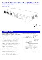
3Com 3C16470B User Manual - Page 3
Nstalling, Witch - baseline
 |
UPC - 662705525358
View all 3Com 3C16470B manuals
Add to My Manuals
Save this manual to your list of manuals |
Page 3 highlights
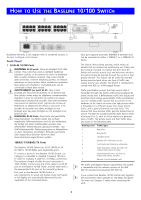
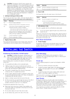
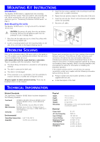
CAUTION: The Baseline 10/100 Switch supports full ! duplex auto-negotiation. If the connected device does not support auto-negotiation, the Switch will operate in half duplex mode (even if the device is operating in full duplex mode). In such a configuration, you may notice some degradation of network performance. 3Com recommends that you use devices that are capable of auto-negotiation (and that you ensure that auto-negotiation is enabled, if it is a configurable option). 2 Activity/Link/Speed Status LEDs The first (top) and third row of LEDs, which are colored yellow or green, show the activity and speed status of the related ports: Status Meaning On The link has been established. Flashing Packets are being received or transmitted on the port. Off If the link has not been established, either nothing is connected to the port, or there is a problem: ■ Check that the attached device is powered on. ■ Check that the cable is the correct type and is not faulty. If these checks do not identify the cause of the problem, it may be that the unit or the device connected to the port is faulty. Contact your supplier for further advice. Green The link is operating at 100 Mbps. Yellow The link is operating at 10 Mbps. 3 Duplex Status LEDs The second and fourth (bottom) row of Status LEDs, which are colored yellow, show the duplex status of the related ports: INSTALLING THE SWITCH Status On Yellow Off Meaning The port is operating in full-duplex mode. The port is operating in half-duplex mode. 4 Power LED The Power LED shows the power status of the Switch: Status On Green Off Meaning The unit is powered on and ready for use. The unit is not receiving power: ■ Check the power cord is connected correctly. ■ If the unit still does not operate, contact your supplier. 5 Self-adhesive Pads The unit is supplied with four self-adhesive rubber pads. You do not need to apply the pads if you intend to rack mount the unit. If the unit is to be part of a free standing stack, apply the pads to each marked corner area on the underside of the unit. Place the unit on top of the lower unit, ensuring that the pads locate with the recesses of the lower unit. Rear Panel Connections 6 Power Supply The Baseline 10/100 Switch automatically adjusts to the supply voltage. Only use the power cord that is supplied with the Baseline 10/100 Switch. Positioning the Baseline 10/100 Switch CAUTION: If installing the Baseline 10/100 Switch in a ! stack of different size SuperStack 3 units, the smaller units must be installed above the larger ones. Do not have a free-standing stack of more than six units. When deciding where to position the Baseline 10/100 Switch ensure that: „ It is accessible and cables can be connected easily. „ Cabling is away from sources of electrical noise such as radios, transmitters and broadband amplifiers, and away from power lines and fluorescent lighting fixtures. „ The Switch is situated away from sources of electrically conductive dust, for example laser printers. „ The AC supply used by the Switch is separate to those used by units that generate high levels of AC noise, for example air conditioning units and laser printers. „ Water or moisture cannot enter the case of the unit. „ Air flow around the unit and through the vents in the side of the case is not restricted (3Com recommends that you provide a minimum of 25 mm (1 in.) clearance). To prolong the operational life of your units: „ Never stack units more than six high if free-standing, and ensure that cables are supported so that they do not cause the stack to fall over. „ Do not place objects on top of any unit or stack. „ Do not obstruct any vents at the sides of the case. Rack Mounting The Baseline 10/100 Switch can be mounted in a 19-inch equipment rack using the Mounting Kit. Refer to "Mounting Kit Instructions" on page 5. Power Up Use the following sequence to power up the Baseline 10/100 Switch: 1 Check the network connections and cables. 2 Connect the power supply cable to the appropriate power socket on the rear panel of the unit; refer to 6 Power Supply. 3 Connect the plug to the power supply outlet socket and switch on the power supply at the socket. When the switch is powered on, the Power LED should be lit on green. If it is not, refer to 4 Power LED. Spot Checks At frequent intervals you should visually check the Baseline 10/100 Switch. Regular checks can give you an early warning of a possible failure; any problems can then be attended to when there will be least effect on users. Check that all external cabling connections are secure and that no cables are pulled taut. If you experience any problems operating the Baseline 10/100 Switch, refer to "Problem Solving" on page 5. 3
-
 1
1 -
 2
2 -
 3
3 -
 4
4 -
 5
5 -
 6
6 -
 7
7 -
 8
8
 |
 |