3Com 3C16470B User Manual - Page 5
Mounting Kit Instructions Problem Solving Technical Information - product
 |
UPC - 662705525358
View all 3Com 3C16470B manuals
Add to My Manuals
Save this manual to your list of manuals |
Page 5 highlights
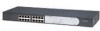
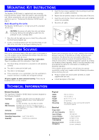
MOUNTING KIT INSTRUCTIONS Introduction The Baseline 10/100 Switch is supplied with two mounting brackets and four screws. These are used for rack-mounting the unit. When mounting the unit, you should take note of the guidelines given in "Positioning the Baseline 10/100 Switch" on page 3. Rack Mounting the Units The Baseline 10/100 Switch is 1U high and will fit a standard 19-inch rack. 3 Insert the two screws supplied in the mounting kit and fully tighten with a suitable screwdriver. 4 Repeat the two previous steps for the other side of the unit. 5 Insert the unit into the 19-inch rack and secure with suitable screws (not provided). 6 Reconnect all cables. CAUTION: Disconnect all cables from the unit before continuing. Remove the self-adhesive pads from the underside of unit, if already fitted. 1 Place the unit the right way up on a hard, flat surface with the front facing towards you. 2 Locate a mounting bracket over the mounting holes on one side of the unit (refer to the figure following step 6). PROBLEM SOLVING Refer to the information about LEDs given earlier in this guide to see if the problem can be identified and rectified. Here are some common problems that can occur: Link Status LED not lit for a port that has a connection. There is a problem with this connection. Check that: „ The device being connected to is powered on and operating correctly. „ The cable is connected at both ends. „ The cable is not damaged. „ If the connection is to a workstation, that the workstation's network interface is installed and configured correctly. All ports appear to show continual activity. There may be broadcast storms on the network. Remove port connections one at a time, waiting a few seconds between each port. If the LEDs go off after removing a port connection, the device that was connected to that port is introducing an excessive amount of broadcast frames to the network (some pieces of network equipment operate by sending out broadcast frames regularly). Refer to the documentation that accompanies the device for information on disabling the broadcast operation. If the problem persists and the unit still does not operate successfully, contact your supplier with the following information before returning the unit: „ Product number and serial number (printed on a label supplied with the unit) „ A brief description of the fault TECHNICAL INFORMATION Related Standards The SuperStack 3 Baseline 10/100 Switch has been designed to the following standards: Functional Safety EMC Emissions Immunity ISO 8802-3, IEEE 802.3 (Ethernet), IEEE 802.3u (Fast Ethernet), IEEE 802.3x (Flow Control), IEEE 802.3d (Bridging) UL 1950, EN 60950, CSA 22.2 #950, IEC 60950 EN 55022 Class A, FCC Part 15 Subpart B Class A, ICES-003 Class A, VCCI Class A, AS/NZS 3548 Class A, CNS 13438 Class A EN 55024 Environmental Operating Temperature 0-40 °C (32-104 °F) Humidity 10-95% (non-condensing) Physical Width Depth Height Weight Mounting 440 mm (17.3 in.) 173 mm (6.8 in.) 44 mm (1.7 in.) or 1U 2.6 kg (5.8 lb) Free standing, or 19 in. rack mounted using the mounting kit supplied Electrical Power Inlet AC Line Frequency Input Voltage Current Rating Maximum Power Consumption Maximum Power Dissipation IEC 320 50/60 Hz 100-240 VAC 1 Amps (maximum) 3C16470: 15 VA 3C16471: 20 VA 3C16470: 52 BTU/hr 3C16471: 68 BTU/hr 5
-
 1
1 -
 2
2 -
 3
3 -
 4
4 -
 5
5 -
 6
6 -
 7
7 -
 8
8
 |
 |
