3Com 3C16476-US User Guide - Page 3
Installation Recommendations - power supply
 |
UPC - 662705452999
View all 3Com 3C16476-US manuals
Add to My Manuals
Save this manual to your list of manuals |
Page 3 highlights
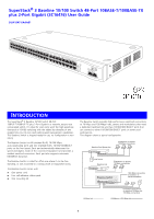
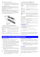
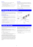
Connecting to another Switch or Hub If you connect two Baseline Switch units together, 3Com recommends that you use the 10/100/1000BASE-T ports on both units for the link. You must use Category 5 cable when connecting the units. 10/100/1000BASE-T connection: To connect a Baseline Switch to another Switch using the 10/100/1000BASE-T port, use a normal 'straight through' or 'cross-over' cable and connect each end to the 10/100/1000BASE-T port on each unit. 100BASE-TX connection: The Baseline Switch can be connected to a SuperStack 3 hub using either a normal 'straight through' or a 'cross-over' cable. Connect any port on the Baseline Switch to any port on the hub, as shown below. The ports on the Baseline Switch are configured as auto-MDI and will automatically detect whether they need to operate in MDI or MDIX mode. 10BASE-T or 100BASE-TX hub Baseline Switch Normal 'straight through' or 'cross-over' TP cable 2 Link Status LEDs for 10BASE-T/100BASE-TX Ports These LEDs illuminate for 2 seconds after power-up. They indicate the status of the ports as follows: Green A 100 Mbps link is present and the port is enabled. Green flashing Packets are being transmitted/received on this port. Yellow A 10 Mbps link is present and the port is enabled. Yellow flashing Packets are being transmitted/received on this port. Off No link is present. 3 Link Status LEDs for 10/100/1000BASE-T Ports These LEDs indicate the status of the ports as follows: Green Green flashing Yellow Yellow flashing Off A 1000 Mbps link is present and the port is enabled. Packets are being transmitted/received on this port. A 10 or 100 Mbps link is present and the port is enabled. Packets are being transmitted/received on this port. No link is present. 4 Power LED This LED illuminates for 2 seconds after power-up, and indicates the following: Green Off The Switch is powered up and operating normally. The Switch is not receiving power, or there is a fault with the power supply unit. 5 Fan Alert LED This LED lights up for 2 seconds after power-up and it shows the current operating state of the fans in the unit. Off Amber flashing Fans operating normally. One or both fans are not operating normally. Refer to "Problem Solving". Rear Panel Connections 6 Power Supply The Baseline Switch automatically adjusts to the supply voltage. Only use the power cord that is supplied with the unit. 7 Self-adhesive Pads The unit is supplied with four self-adhesive rubber pads. You do not need to apply the pads if you intend to rack mount the unit. If the unit is to be part of a free standing stack, apply the pads to each marked corner area on the underside of the unit. Place the unit on top of the lower unit, ensuring that the pads locate with the recesses of the lower unit. INSTALLATION RECOMMENDATIONS Positioning the Switch When deciding where to position the Baseline Switch ensure: „ It is accessible and cables can be connected easily. „ Cabling is away from sources of electrical noise. These include lift shafts, microwave ovens, and air conditioning units. Electromagnetic fields can interfere with the signals on copper cabling and introduce errors, therefore slowing down your network. „ Water or moisture cannot enter the case of the unit. „ Air flow around the unit and through the vents in the side of the case is not restricted (3Com recommends that you provide a minimum of 25 mm (1 in.) clearance). „ The air is as free from dust as possible. „ Temperature operating limits are not likely to be exceeded. It is recommended that the unit is installed in a clean, air conditioned environment. It is always good practice to wear an anti-static wrist strap when installing network equipment, connected to a ground point. If one is not available, try to keep in contact with a grounded rack and avoid touching the unit's ports and connectors, if possible. Static discharge can cause reliability problems in your equipment. Rack Mounting or Free Standing The unit can be mounted in a 19-inch equipment rack using the Mounting Kit or it can be free-standing. Instructions for fitting the Mounting Kit are on page 4. Do not place objects on top of the unit or stack. CAUTION: If installing the Baseline Switch in a free standing ! stack of different size SuperStack 3 units, the smaller units must be installed above the larger ones. Do not have a free standing stack of more than six units. Power Supply Power problems can be the cause of serious failures and downtime in your network. Ensure that the power input to your system is clean and free from sags and surges to avoid unforeseen network outages. We recommend that you install power conditioning, especially in areas prone to black outs, power dips and electrical storms. The unit is intended to be grounded. Ensure it is connected to earth ground during normal use. Installing proper grounding helps to avoid damage from lightning and power surges. 3
-
 1
1 -
 2
2 -
 3
3 -
 4
4 -
 5
5 -
 6
6 -
 7
7 -
 8
8
 |
 |