3Com 3C16476-US User Guide - Page 4
Mounting Kit Instructions Problem Solving - user guide
 |
UPC - 662705452999
View all 3Com 3C16476-US manuals
Add to My Manuals
Save this manual to your list of manuals |
Page 4 highlights
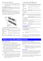
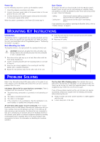
Power Up Use the following sequence to power up the Baseline Switch: 1 Check the network connections and cables. 2 Connect the power supply cable to the power socket on the rear panel of the unit; refer to 6. 3 Connect the plug to the power supply outlet socket and switch on the power supply at the socket. When the switch is powered on, the Power LED should stay lit. Spot Checks At frequent intervals you should visually check the Baseline Switch. Regular checks can give you an early warning of a possible failure; any problems can then be attended to when there will be least effect on users. Check the following: Cabling Cooling fans Check that all external cabling connections are secure and that no cables are pulled taut. Check that the Fan Alert LED is not flashing amber. If you experience any problems operating the Baseline Switch, refer to "Problem Solving" on page 4. MOUNTING KIT INSTRUCTIONS Introduction The Baseline Switch is supplied with two mounting brackets and four screws. These are used for rack mounting the unit. When mounting the unit, you should take note of the guidelines given in "Positioning the Switch" on page 3. Rack Mounting the Units The Baseline Switch is 1U high and will fit a standard 19-inch rack. CAUTION: Disconnect all cables from the unit before continuing. Remove the self-adhesive pads from the underside of unit, if already fitted. 1 Place the unit the right way up on a hard, flat surface with the front facing towards you. 2 Locate a mounting bracket over the mounting holes on one side of the unit. 3 Insert the two screws supplied in the mounting kit and fully tighten with a suitable screwdriver. 4 Repeat the two previous steps for the other side of the unit. 5 Insert the unit into the 19-inch rack and secure with suitable screws (not provided). 6 Reconnect all cables. PROBLEM SOLVING Refer to the information about LEDs given earlier in this guide to see if the problem can be identified and rectified. Here are some common problems that can occur: Link Status LED not lit for a port that has a connection. There is a problem with this connection. Check that: „ The device being connected to is powered on and operating correctly. „ The cable is connected at both ends. „ The cable is not damaged. „ If the connection is to a workstation, that the workstation's net- work interface is installed and configured correctly. All Link Status LEDs appear to be lit continually. There may be broadcast storms on the network. Remove port connections one at a time, waiting a few seconds between each port. If the LEDs go off after removing a port connection, the device that was connected to that port is introducing an excessive amount of broadcast frames to the network (some pieces of network equipment operate by sending out broadcast frames regularly). Refer to the documentation that accompanies the device for information on disabling the broadcast operation. The Fan Alert LED is flashing amber. This indicates that one or both of the internal fans are operating in a non-optimal mode. The fan(s) may be turning at a lower than expected speed, or may have stopped turning. Power the unit off and on again. If any of these problems persist and the unit still does not operate successfully, contact your supplier with the following information before returning the unit: „ Product number and serial number (printed on a label supplied with the unit) „ A brief description of the fault 4
-
 1
1 -
 2
2 -
 3
3 -
 4
4 -
 5
5 -
 6
6 -
 7
7 -
 8
8
 |
 |
