ASRock 980DE3/U3S3 User Manual - Page 21
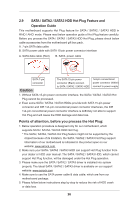
Front Panel Audio Header
 |
View all ASRock 980DE3/U3S3 manuals
Add to My Manuals
Save this manual to your list of manuals |
Page 21 highlights
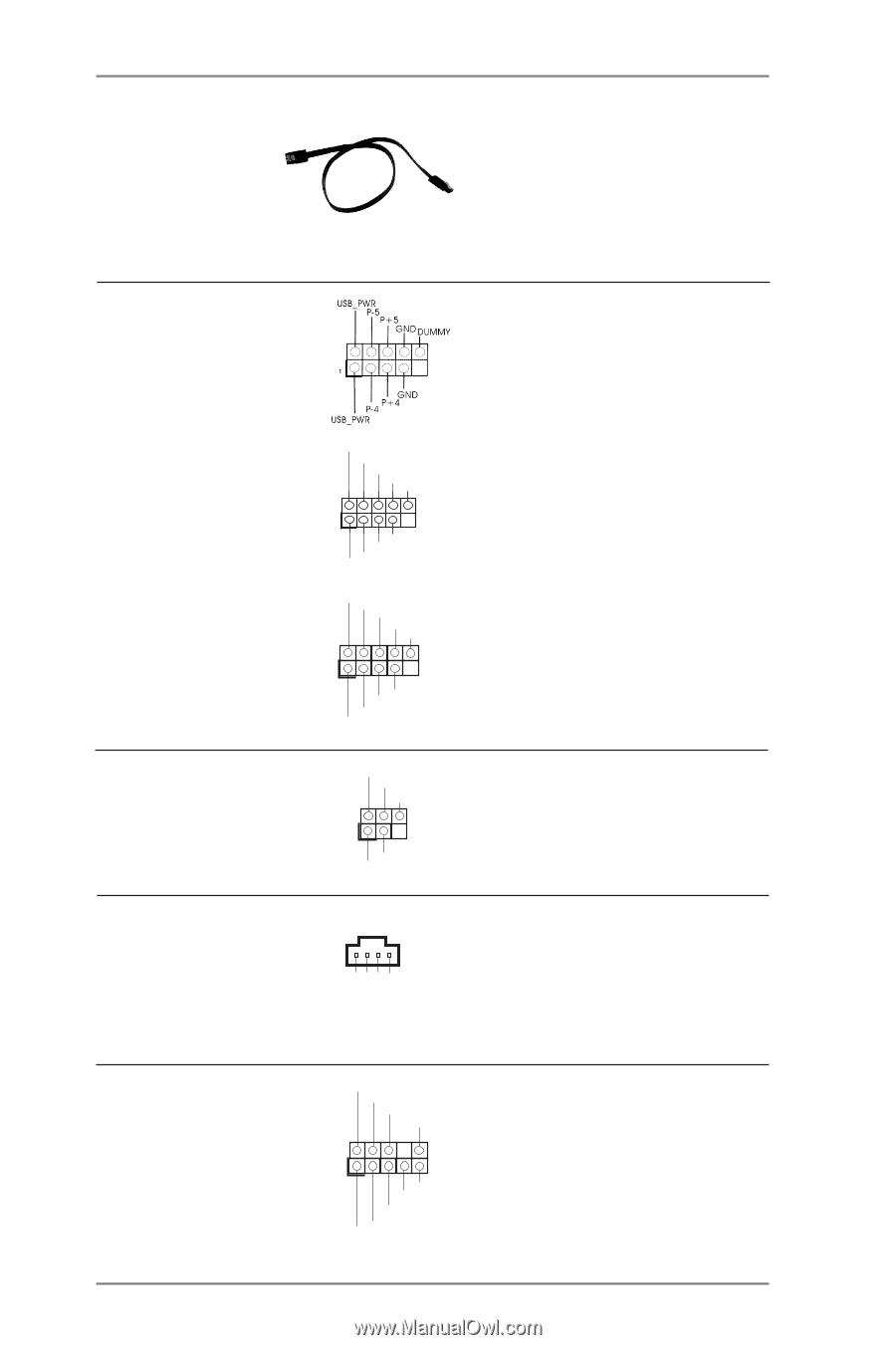
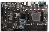
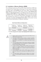
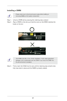
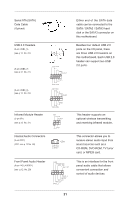
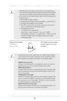
Serial ATA (SATA) Data Cable (Optional) USB 2.0 Headers (9-pin USB4_5) (see p.12 No. 22) (9-pin USB6_7) (see p.12 No. 21) (9-pin USB8_9) (see p.12 No. 23) USB_PWR P-7 P+7 GND DUMMY 1 GND P+6 P-6 USB_PWR USB_PWR P-9 P+9 GND DUMMY 1 GND P+8 P-8 USB_PWR Infrared Module Header (5-pin IR1) (see p.12 No. 31) IRTX +5VSB DUMMY 1 GND IRRX Internal Audio Connectors (4-pin CD1) (CD1: see p.12 No. 28) CD1 CD-L GND GND CD-R Either end of the SATA data cable can be connected to the SATA / SATA2 / SATA3 hard disk or the SATA3 connector on this motherboard. Besides four default USB 2.0 ports on the I/O panel, there are three USB 2.0 headers on this motherboard. Each USB 2.0 header can support two USB 2.0 ports. This header supports an optional wireless transmitting and receiving infrared module. This connector allows you to receive stereo audio input from sound sources such as a CD-ROM, DVD-ROM, TV tuner card, or MPEG card. Front Panel Audio Header (9-pin HD_AUDIO1) (see p.12 No. 29) GND PRESENCE# MIC_RET OUT_RET 1 OUT2_L J_SENSE OUT2_R MIC2_R MIC2_L This is an interface for the front panel audio cable that allows convenient connection and control of audio devices. 21
-
 1
1 -
2
-
3
-
4
-
5
-
6
-
7
-
8
-
9
-
10
-
11
-
12
-
13
-
14
-
15
-
 16
16 -
 17
17 -
 18
18 -
 19
19 -
 20
20 -
 21
21 -
 22
22 -
 23
23 -
 24
24 -
 25
25 -
 26
26 -
27
-
28
-
29
-
30
-
31
-
32
-
33
-
34
-
35
-
36
-
37
-
38
-
39
-
40
-
41
-
42
-
43
-
44
-
45
-
46
-
47
-
48
-
49
-
50
-
51
-
52
 |
 |