ASRock AD410PV User Manual
ASRock AD410PV Manual
 |
View all ASRock AD410PV manuals
Add to My Manuals
Save this manual to your list of manuals |
ASRock AD410PV manual content summary:
- ASRock AD410PV | User Manual - Page 1
AD510PV / AD410PV User Manual Version 1.0 Published March 2010 Copyright©2010 ASRock INC. All rights reserved. 1 - ASRock AD410PV | User Manual - Page 2
purchaser for backup purpose, without written consent of ASRock Inc. Products and corporate names appearing in this manual may or may not be registered trademarks or copyrights USA ONLY The Lithium battery adopted on this motherboard contains Perchlorate, a toxic substance controlled in Perchlorate - ASRock AD410PV | User Manual - Page 3
20 2.10 SATA / SATAII HDD Hot Plug Feature and Operation Guide 21 2.11 Driver Installation Guide 23 2.12 Installing Windows® 7 / 7 64-bit / VistaTM 24 2.13 Untied Overclocking Technology 25 3 BIOS SETUP UTILITY 26 3.1 Introduction 26 3.1.1 BIOS Menu Bar 26 3.1.2 Navigation Keys 27 3.2 - ASRock AD410PV | User Manual - Page 4
42 3.6 Boot Screen 43 3.6.1 Boot Settings Configuration 43 3.7 Security Screen 44 3.8 Exit Screen 45 4 Software Support 46 4.1 Install Operating System 46 4.2 Support CD Information 46 4.2.1 Running Support CD 46 4.2.2 Drivers Menu 46 4.2.3 Utilities Menu 46 4.2.4 Contact Information 46 4 - ASRock AD410PV | User Manual - Page 5
Contents ASRock AD510PV / AD410PV Motherboard (Mini-ITX Form Factor: 6.7-in x 6.7-in, 17.0 cm x 17.0 cm) One Bundled Intel® Dual-Core AtomTM Processor D510 (AD510PV) One Bundled Intel® AtomTM Processor D410 (AD410PV) ASRock AD510PV / AD410PV Quick Installation Guide ASRock AD510PV / AD410PV Support - ASRock AD410PV | User Manual - Page 6
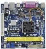
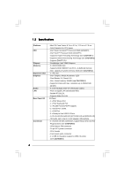
Memory Expansion Slot Graphics Audio LAN Rear Panel I/O Connector - Mini-ITX Form Factor: 6.7-in x 6.7-in, 17.0 cm x 17.0 cm - Solid Capacitor for CPU power - Intel® Dual-Core AtomTM Processor D510 (AD510PV) - Intel® AtomTM Processor D410 (AD410PV) - Supports Hyper-Threading Technology (see CAUTION - ASRock AD410PV | User Manual - Page 7
- 4Mb AMI BIOS - AMI Legal BIOS - Supports "Plug and Play" - ACPI 1.1 Compliance Wake Up Events - Supports jumperfree - AMBIOS 2.3.1 Support - VCCM, SB Voltage Multi-adjustment - Supports Smart BIOS Support CD - Drivers, Utilities, AntiVirus Software (Trial Version), ASRock Software Suite - ASRock AD410PV | User Manual - Page 8
2. This motherboard supports Untied Overclocking the "SATAII Hard Disk Setup Guide" on page 19 to adjust ASRock OC Tuner. ASRock website: http://www.asrock.com 8. ASRock Instant Flash is a BIOS flash utility embedded in Flash ROM. This convenient BIOS update tool allows you to update system BIOS - ASRock AD410PV | User Manual - Page 9
regulated by European Union to define the power consumption for the completed system. According to EuP, the total AC power of the completed system shall be under 1.00W in off mode condition. To meet EuP standard, an EuP ready motherboard and an EuP ready power supply are required. According to Intel - ASRock AD410PV | User Manual - Page 10
1.3 Motherboard Layout 1 2 34 5 17.0cm (6.7 in) 1 PS2_USB_PWR1 CPU_FAN1 Super IO 6 ErP/EuP White) 5 2 x 240-pin DDR2 DIMM Slots 14 BIOS SPI Chip (Dual Channel: DDRII_1, DDRII_2; Yellow) 15 PCI Slot (PCI1) 6 ATX Power Connector (ATXPWR1) 16 Internal Audio Connector: CD1 (Black) - ASRock AD410PV | User Manual - Page 11
find "VIA HD Audio Deck" tool on your system. Please follow below instructions according to the OS you install. For Windows® XP / XP 64-bit click "Speaker". Then you are allowed to select "2 Channel" or "4 Channel". Click "Power" to save your change. For Windows® 7 / 7 64-bit / VistaTM / VistaTM - ASRock AD410PV | User Manual - Page 12
AD510PV / AD410PV is a Mini-ITX form factor (6.7" x 6.7", 17.0 x 17.0 cm) motherboard. Before you install the motherboard, study the configuration of your chassis to ensure that the motherboard fits into it. Make sure to unplug the power cord before installing or removing the motherboard - ASRock AD410PV | User Manual - Page 13
Modules (DIMM) AD510PV / AD410PV motherboard provides two 240-pin DDR2 (Double Data Rate 2) DIMM slots. It is not allowed to install a DDR memory module into DDR2 slot;otherwise, this motherboard and DIMM may be damaged. Installing a DIMM Please make sure to disconnect power supply before adding - ASRock AD410PV | User Manual - Page 14
is 1 PCI slot on this motherboard. PCI slot: PCI slot is used to install expansion cards that have the 32-bit PCI interface. Installing an expansion card Step 1. Before installing the expansion card, please make sure that the power supply is switched off or the power cord is unplugged. Please read - ASRock AD410PV | User Manual - Page 15
enable +5VSB (standby) for PS/2 +5V +5VSB or USB wake up events. Note: To select +5VSB, it requires 2 Amp and higher standby current provided by power supply. 15 - ASRock AD410PV | User Manual - Page 16
connected to the SATA / SATAII hard disk or the SATAII connector on the motherboard. Besides four default USB 2.0 ports on the I/O panel, there are two USB 2.0 headers on this motherboard. Each USB 2.0 header can support two USB 2.0 ports. This connector allows you to receive stereo audio input from - ASRock AD410PV | User Manual - Page 17
must support HDA to function correctly. Please follow the instruction in our manual and chassis manual to install connect them for AC'97 audio panel. E. Enter BIOS Setup Utility. Enter Advanced Settings, and then select . Though this motherboard provides 4-Pin CPU fan (Quiet Fan) support, the 3-Pin - ASRock AD410PV | User Manual - Page 18
12 24 Please connect an ATX power supply to this connector. 1 13 Though this motherboard provides 24-pin ATX power connector, 12 24 it can still work if you adopt a traditional 20-pin ATX power supply. To use the 20-pin ATX power supply, please plug your power supply along with Pin 1 and - ASRock AD410PV | User Manual - Page 19
guide. Some default setting of SATAII hard disks may not be at SATAII mode, which operate with the best performance. In order to enable SATAII function, please follow the below instruction website for details: http://www.hitachigst.com/hdd/support/download.htm The above examples are just for your - ASRock AD410PV | User Manual - Page 20
supports Serial ATA (SATA) / Serial ATAII (SATAII) hard disks. You may install SATA / SATAII hard disks on this motherboard for internal storage devices. This section will guide remove the SATA / SATAII HDDs while the system is still power-on and in working condition. However, please note that it - ASRock AD410PV | User Manual - Page 21
is installed into system properly. The latest SATA / SATAII driver is available on our support website: www.asrock.com 4. Make sure to use the SATA power cable & data cable, which are from our motherboard package. 5. Please follow below instructions step by step to reduce the risk of HDD crash or - ASRock AD410PV | User Manual - Page 22
instruction sequence to process the Hot Plug, improper procedure will cause the SATA / SATAII HDD damage and data loss. Step 1 Please connect SATA power cable 1x4-pin end Step 2 Connect SATA data cable to (White) to the power supply 1x4-pin cable. the motherboard's SATAII connector. SATA power - ASRock AD410PV | User Manual - Page 23
2.11 Driver Installation Guide To install the drivers to your system, please insert the support CD to your optical drive first. Then, the drivers compatible to your system can be auto-detected and listed on the support CD driver page. Please follow the order from up to bottom side to install those - ASRock AD410PV | User Manual - Page 24
SATA / SATAII HDDs without RAID functions, please follow below steps. Using SATA / SATAII HDDs with NCQ function STEP 1: Set Up BIOS. A. Enter BIOS SETUP UTILITY Advanced screen Storage Configuration. B. Set the option "SATA Operation Mode" to [AHCI]. STEP 2: Install Windows® 7 / 7 64-bit / VistaTM - ASRock AD410PV | User Manual - Page 25
2.13 Untied Overclocking Technology This motherboard supports Untied Overclocking Technology, which means during overclocking, FSB enjoys better margin due to fixed PCI bus. Before you enable Untied Overclocking function, please enter "Overclock Mode" option of BIOS setup to set the selection from [ - ASRock AD410PV | User Manual - Page 26
SETUP UTILITY to configure your system. The BIOS FWH chip on the motherboard stores the BIOS SETUP UTILITY. You may run the BIOS SETUP UTILITY when you start up the computer. Please press during the Power-On-Self-Test (POST) to enter the BIOS SETUP UTILITY, otherwise, POST will continue with - ASRock AD410PV | User Manual - Page 27
Boot Security Exit System Overview System Time System Date [14:00:09] [Mon 11/02/2009] BIOS Version : AD510PV P1.00 Processor Type : Intel (R) Atom (TM) CPU D510 @ 1.66GHz (64bit) Processor Speed : 1666MHz Microcode Update : 106CA/107 Cache Size : 1024KB Total Memory DDRII1 DDRII2 - ASRock AD410PV | User Manual - Page 28
Boot Security Exit System Overview System Time System Date [14:00:09] [Mon 11/02/2009] BIOS Version : AD410PV P1.00 Processor Type : Intel (R) Atom (TM) CPU D510 @ 1.66GHz (64bit) Processor Speed : 1666MHz Microcode Update : 106CA/107 Cache Size : 1024KB Total Memory DDRII1 DDRII2 - ASRock AD410PV | User Manual - Page 29
screen, you can set up overclocking features. BIOS SETUP UTILITY Main OC Tweaker Advanced H/W Monitor Boot Auto] Would you like to save current setting as Overclocking may cause damage to your CPU and motherboard. It should be done at your own risk and expense. Select Screen Select Item Enter Go - ASRock AD410PV | User Manual - Page 30
DRAM Timing Control BIOS SETUP UTILITY OC Tweaker DRAM Timing Control Standard Memory Info : 6-6-6-18-52-6-3-3-3 DRAM tCL [Auto] DRAM tRCD [Auto] DRAM tRP [Auto] DRAM tRAS [Auto] DRAM - ASRock AD410PV | User Manual - Page 31
VCORE Voltage Use this to select VCORE Voltage. Configuration options: [Auto], [1.107V] to [1.252V]. The default value of this feature is [Auto]. VCCM(DRAM) Voltage Use this to select VCCM(DRAM) Voltage. Configuration options: [Auto], [1.794V] to [2.201V]. The default value of this feature is [Auto - ASRock AD410PV | User Manual - Page 32
cause system to malfunction. CPU Configuration Chipset Configuration ACPI Configuration Storage Configuration PCIPnP Configuration SuperIO Configuration USB Configuration BIOS Update Utility ASRock Instant Flash Select Screen Select Item Enter Go to Sub Screen F1 General Help F9 Load Defaults F10 - ASRock AD410PV | User Manual - Page 33
Configuration BIOS SETUP read-only item, which displays the ratio actual value of this motherboard. CPU Thermal Throttling You may select [Enabled] to enable P4 computer system with an Intel Pentium® 4 processor that supports Hyper-Threading technology and an operating system that includes - ASRock AD410PV | User Manual - Page 34
BIOS Technology) is an architecture that offers breakthrough performance for the motherboard through efficient memory utilization. In Fixed mode, a fixed-size to the graphics core. In DVMT mode, the graphics driver allocates memory as needed for running graphics applications and is cooperatively - ASRock AD410PV | User Manual - Page 35
Onboard HD Audio Select [Auto], [Enabled] or [Disabled] for the onboard HD Audio feature. If you select [Auto], the onboard HD Audio will be disabled when PCI Sound Card is plugged. Front Panel Select [Auto], [Enabled] or [Disabled] for the onboard HD Audio Front Panel. OnBoard Lan This allows you - ASRock AD410PV | User Manual - Page 36
if the system supports it. Check Ready Bit Use this item to enable or disable the feature Check Ready Bit. Restore on AC/Power Loss This allows you to set the power state after an unexpected AC/Power loss. If [Power Off] is selected, the AC/Power remains off when the power recovers. If [Power On] is - ASRock AD410PV | User Manual - Page 37
The default value is [IDE]. AHCI (Advanced Host Controller Interface) supports NCQ and other new features that will improve SATA disk performance but will use the "SATAII_1" as the example in the following instruction. BIOS SETUP UTILITY Advanced SATAII_1 Device Vendor Size LBA Mode Block Mode - ASRock AD410PV | User Manual - Page 38
After selecting the hard disk information into BIOS, use a disk utility, such as FDISK, to partition and format the new IDE hard disk drives. This is necessary so that you can write or - ASRock AD410PV | User Manual - Page 39
3.4.5 PCIPnP Configuration BIOS SETUP UTILITY Advanced Advanced PCI / PnP Settings PCI Latency Timer PCI IDE BusMaster [32] [Enabled] Value in units of PCI clocks for PCI device latency - ASRock AD410PV | User Manual - Page 40
Parallel Port Address Parallel Port Mode EPP Version ECP Mode DMA Channel Parallel Port IRQ [3F8 / IRQ4] [378] [ECP + EPP] [1.9] [DMA3] [IRQ7] Allow BIOS to Enable or Disable Floppy Controller. +F1 F9 F10 ESC Select Screen Select Item Change Option General Help Load Defaults Save and Exit Exit - ASRock AD410PV | User Manual - Page 41
Use this item to enable or disable the USB 2.0 support. Legacy USB Support Use this option to select legacy support for USB devices. There are four configuration options: [Enabled], [Auto], [Disabled] and [BIOS Setup Only]. The default value is [Enabled]. Please refer to below descriptions for - ASRock AD410PV | User Manual - Page 42
monitor the status of the hardware on your system, including the parameters of the CPU temperature, motherboard temperature, CPU fan speed, chassis fan speed, and the critical voltage. BIOS SETUP UTILITY Main OC Tweaker Advanced H/W Monitor Boot Security Exit Hardware Health Event Monitoring CPU - ASRock AD410PV | User Manual - Page 43
v02.54 (C) Copyright 1985-2005, American Megatrends, Inc. 3.6.1 Boot Settings Configuration BIOS SETUP UTILITY Boot Boot Settings Configuration Full Screen Logo AddOn ROM Display Boot Logo Boot Logo". Configuration options: [Auto], [EuP], [Scenery] and [ASRock]. The default value is [Auto]. 43 - ASRock AD410PV | User Manual - Page 44
this section, you may set or change the supervisor/user password for the system. For the user password, you may also clear it. BIOS SETUP UTILITY Main OC Tweaker Advanced H/W Monitor Boot Security Exit Security Settings Supervisor Password : Not Installed User Password : Not Installed Change - ASRock AD410PV | User Manual - Page 45
Monitor Boot Security Exit Exit Options Save Changes and Exit Discard Changes and Exit Discard Changes Load BIOS Defaults Load Performance Setup Default (IDE/SATA) Load Performance Setup AHCI Mode Load Power Saving Setup Default Exit system setup after saving the changes. F10 key can be used for - ASRock AD410PV | User Manual - Page 46
install the necessary drivers to activate the devices. 4.2.3 Utilities Menu The Utilities Menu shows the applications software that the motherboard supports. Click on a specific item then follow the installation wizard to install it. 4.2.4 Contact Information If you need to contact ASRock or want to
-
 1
1 -
 2
2 -
 3
3 -
 4
4 -
 5
5 -
 6
6 -
 7
7 -
8
-
9
-
10
-
11
-
12
-
13
-
14
-
15
-
16
-
17
-
18
-
19
-
20
-
21
-
22
-
23
-
24
-
25
-
26
-
27
-
28
-
29
-
30
-
31
-
32
-
33
-
34
-
35
-
36
-
37
-
38
-
39
-
40
-
41
-
42
-
43
-
44
-
45
-
46
 |
 |

1
AD510PV /
AD410PV
User Manual
Version 1.0
Published March 2010
Copyright©2010 ASRock INC. All rights reserved.