ASRock P45XE-R User Manual
ASRock P45XE-R Manual
 |
View all ASRock P45XE-R manuals
Add to My Manuals
Save this manual to your list of manuals |
ASRock P45XE-R manual content summary:
- ASRock P45XE-R | User Manual - Page 1
P45XE-WiFiN / P45XE-R / P45XE User Manual Version 1.1 Published September 2008 Copyright©2008 ASRock INC. All rights reserved. 1 - ASRock P45XE-R | User Manual - Page 2
purchaser for backup purpose, without written consent of ASRock Inc. Products and corporate names appearing in this manual may or may not be registered trademarks or copyrights USA ONLY The Lithium battery adopted on this motherboard contains Perchlorate, a toxic substance controlled in Perchlorate - ASRock P45XE-R | User Manual - Page 3
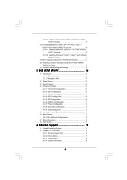
Specifications 6 1.3 Motherboard Layout (P45XE-WiFiN / P45XE-R 11 1.4 Motherboard Layout (P45XE 12 1.5 ASRock DualLAN_SPDIF I/O (P45XE-WiFiN 13 1.6 ASRock DualLAN_SPDIF I/O (P45XE-R 14 1.7 ASRock SPDIF I/O Plus (P45XE 15 1.8 ASRock WiFi-802.11n Module Specifications (For P45XE-WiFiN Only 16 - ASRock P45XE-R | User Manual - Page 4
/ VistaTM 64-bit Without RAID Functions 49 2.20 DTS Operation Guide (For P45XE-WiFiN Only 50 2.21 Teaming Function Operation Guide (For P45XE-WiFiN / P45XE-R Only 52 2.22 Untied Overclocking Technology 55 3 BIOS SETUP UTILITY 56 3.1 Introduction 56 3.1.1 BIOS Menu Bar 56 3.1.2 Navigation - ASRock P45XE-R | User Manual - Page 5
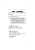
Contents ASRock P45XE-WiFiN / P45XE-R / P45XE Motherboard (ATX Form Factor: 12.0-in x 8.8-in, 30.5 cm x 22.4 cm) ASRock P45XE-WiFiN / P45XE-R / P45XE Quick Installation Guide ASRock P45XE-WiFiN / P45XE-R / P45XE Support CD ASRock WiFi-802.11n Module Operation Guide (For P45XE-WiFiN Only) Motherboard - ASRock P45XE-R | User Manual - Page 6
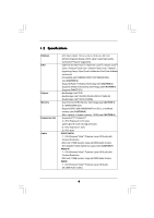
-Threading Technology (see CAUTION 2) - Supports Untied Overclocking Technology (see CAUTION 3) - Supports EM64T CPU - Northbridge: Intel® P45 - Southbridge: Intel® ICH10R (P45XE-WiFiN / P45XE-R) - Southbridge: Intel® ICH10 (P45XE) - Dual Channel DDR2 Memory Technology (see CAUTION 4) - 4 x DDR2 - ASRock P45XE-R | User Manual - Page 7
Speaker/Microphone (see CAUTION 8) - 6 x SATAII 3.0Gb/s connectors, support RAID (RAID 0, RAID 1, RAID 10, RAID 5 and Intel Matrix Storage), NCQ, AHCI and "Hot Plug" functions (see CAUTION 9) * RAID functions are for P45XE-WiFiN / P45XE-R only - 2 x eSATAII 3.0Gb/s connectors (shared with 2 SATAII - ASRock P45XE-R | User Manual - Page 8
1394 header (P45XE-WiFiN / P45XE-R) - CPU/Chassis FAN connector - 24 pin ATX power connector - 8 pin 12V power connector - CD in header - Front panel audio connector - 2 x USB 2.0 headers (support 4 USB 2.0 ports) (see CAUTION 11) - 1 x USB/WiFi header (see CAUTION 12) BIOS Feature - 8Mb - ASRock P45XE-R | User Manual - Page 9
motherboard supports Untied Overclocking Technology. Please read "Untied Overclocking Technology" on page 55 for details. 4. This motherboard supports Dual Channel Memory Technology. Before you implement Dual Channel Memory Technology, make sure to read the installation guide of memory modules - ASRock P45XE-R | User Manual - Page 10
on the motherboard functions properly and unplug the power cord, then plug it back again. To improve heat dissipation, remember to spray thermal grease between the CPU and the heatsink when you install the PC system. 17. ASRock WiFi-802.11n module and RAID / AHCI functions are not supported under - ASRock P45XE-R | User Manual - Page 11
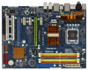
P45 IDE1 Top: SIDE SPK Center: REAR SPK Bottom: CTR BASS ATX12V1 Chipset LAN PHY Top: LINE IN Center: FRONT Bottom: MIC IN PCIE1 LAN PHY RoHS PCI Express 2.0 AUDIO CODEC CD1 HD_AUDIO1 1 PCIE2 PCIE3 PCIE4 1 USB/WIFI PCIE5 VIA VT6330 8Mb BIOS FRONT_1394 1 Intel ICH10R Super - ASRock P45XE-R | User Manual - Page 12
Intel P45 IDE1 ATX12V1 Chipset LAN PHY P45XE Top: LINE IN Center: FRONT Bottom: MIC IN PCIE1 RoHS PCI Express 2.0 AUDIO CODEC CD1 HD_AUDIO1 1 PCIE2 PCIE3 PCIE4 1 USB/WIFI PCIE5 8Mb BIOS Intel 775-Pin CPU Socket ATX Power Connector (ATXPWR1) 9 IDE1 Connector (IDE1, Blue) 10 SPI BIOS - ASRock P45XE-R | User Manual - Page 13
1.5 ASRock DualLAN_SPDIF I/O (P45XE-WiFiN) 1 2 3 4 15 16 5 6 9 7 10 8 11 18 17 1 PS/2 Mouse Port (Green) 2 to connect a front panel audio cable to the front panel audio header. After restarting your computer, you will find "Mixer" tool on your system. Please select "Mixer ToolBox" , - ASRock P45XE-R | User Manual - Page 14
1.6 ASRock DualLAN_SPDIF I/O (P45XE-R) 1 2 3 4 15 16 5 6 9 7 10 8 11 18 17 1 PS/2 Mouse Port (Green) 2 to connect a front panel audio cable to the front panel audio header. After restarting your computer, you will find "Mixer" tool on your system. Please select "Mixer ToolBox" , click - ASRock P45XE-R | User Manual - Page 15
1.7 ASRock SPDIF I/O Plus (P45XE) 1 2 16 15 3 13 14 12 11 4 7 5 8 6 9 10 1 PS/2 Mouse Port (Green) 2 to connect a front panel audio cable to the front panel audio header. After restarting your computer, you will find "Mixer" tool on your system. Please select "Mixer ToolBox" , click - ASRock P45XE-R | User Manual - Page 16
1.8 ASRock WiFi-802.11n Module Specifications (For P45XE-WiFiN Only) ASRock WiFi-802.11n module is an easy-to-use wireless local area network (WLAN) adapter to support WiFi+AP function. With ASRock WiFi-802.11n module, you can easily create a wireless environment and enjoy the convenience of - ASRock P45XE-R | User Manual - Page 17
Precautions Take note of the following precautions before you install motherboard components or change any motherboard settings. 1. Unplug the power cord from the wall socket before touching any component. 2. To avoid damaging the motherboard components due to static electricity, NEVER place your - ASRock P45XE-R | User Manual - Page 18
2.3 CPU Installation For the installation of Intel 775-LAND CPU, please follow the steps below. 775-Pin Socket Overview Before you insert the 775-LAND CPU into the socket, please check if the CPU surface is unclean or if there is any bent pin on the socket. Do not force to insert the CPU into the - ASRock P45XE-R | User Manual - Page 19
finger and thumb to support the load plate edge, engage PnP cap with right hand thumb and peel the cap from the socket while pressing on center cap. 2. This cap must be placed if returning the motherboard for after service. Step 4. Close the socket: Step 4-1. Rotate the load plate onto the IHS. - ASRock P45XE-R | User Manual - Page 20
2.4 Installation of CPU Fan and Heatsink This motherboard is equipped with 775-Pin socket that supports Intel 775-LAND CPU. Please adopt the type of heatsink and cooling fan compliant with Intel 775-LAND CPU to dissipate heat. Before you installed the heatsink, you need to spray thermal interface - ASRock P45XE-R | User Manual - Page 21
2.5 Installation of Memory Modules (DIMM) This motherboard provides four 240-pin DDR2 (Double Data Rate 2) DIMM slots, and supports Dual Channel Memory Technology. For dual channel configuration, you always need to install identical (the same brand, speed, size and chip-type) DDR2 DIMM pair in the - ASRock P45XE-R | User Manual - Page 22
matches the break on the slot. notch break notch break The DIMM only fits in one correct orientation. It will cause permanent damage to the motherboard and the DIMM if you force the DIMM into the slot at incorrect orientation. Step 3. Firmly insert the DIMM into the slot until the retaining - ASRock P45XE-R | User Manual - Page 23
PCI Express graphics cards to support CrossFireTM function. 1. If you plan to install only one PCI Express VGA card on this motherboard, please install it on PCIE2 and CrossFireTM setup procedures, please refer to "CrossFireTM Operation Guide" on page 24. Installing an expansion card Step 1. Before - ASRock P45XE-R | User Manual - Page 24
Operation Guide This motherboard supports CrossFireTM supported with Windows® XP with Service Pack 2 and VistaTM OS. Please check AMD website for ATITM CrossFireTM driver updates. What graphics cards work with CrossFireTM? A complete CrossFireTM system requires a CrossFireTM Ready motherboard - ASRock P45XE-R | User Manual - Page 25
CrossFireTM components, a CrossFireTM Ready graphics card, a CrossFireTM Ready motherboard and a CrossFireTM Edition co-processor graphics card, must be in the future, please refer to ATITM graphics card manuals for detailed installation guide. Step 1. Install one Radeon graphics card to PCIE2 - ASRock P45XE-R | User Manual - Page 26
your computer and boot into OS. Step 6. Remove the ATITM driver if you have any VGA driver driver updates. Step 7. Step 8. Install the required drivers to your system. For Windows® XP OS: A. ATITM recommends Windows® XP Service Pack 2 or higher to be installed (If you have Windows® XP Service - ASRock P45XE-R | User Manual - Page 27
Step 9. Install the VGA card drivers to your system, and restart your computer. Then you will find "ATI Catalyst Control Center" on your Windows® taskbar. ATI Catalyst Control infringe. * For further information of ATITM CrossFireTM technology, please check AMD website for updates and details. 27 - ASRock P45XE-R | User Manual - Page 28
Display Feature This motherboard supports Surround Display upgrade. With the external add-on PCI Express VGA cards, you can easily enjoy the benefits of Surround Display feature. For the detailed instruction, please refer to the document at the following path in the Support CD: ..\ Surround Display - ASRock P45XE-R | User Manual - Page 29
the motherboard connect the black end to the IDE devices 80-conductor ATA 66/100/133 cable Note: Please refer to the instruction of your Port 5) SATAII_4 (Port 3) These six Serial ATAII (SATAII) connectors support SATA data cables for internal storage devices. The current SATAII interface - ASRock P45XE-R | User Manual - Page 30
motherboard. Each USB 2.0 header can support two USB 2.0 ports. USB/WiFi Header (11-pin USB/WIFI) (see p.11 No. 31 or p.12 No. 30) +5V P- P+ GND N/C +3V 1 P- P+ GND N/C +5V This header can be used to support 2 USB 2.0 ports. It can also be used to support WiFi+AP function with ASRock WiFi-802 - ASRock P45XE-R | User Manual - Page 31
supports Jack Sensing, but the panel wire on the chassis must support HDA to function correctly. Please follow the instruction in our manual and chassis manual need to connect them for AC'97 audio panel. E. Enter BIOS Setup Utility. Enter Advanced Settings, and then select Chipset Configuration. - ASRock P45XE-R | User Manual - Page 32
cable 1 GND 2 +12V to this connector and match 3 4 CPU_FAN_SPEED FAN_SPEED_CONTROL the black wire to the ground pin. Though this motherboard provides 4-Pin CPU fan (Quiet Fan) support, the 3-Pin CPU fan still can work successfully even without the fan speed control function. If you plan to - ASRock P45XE-R | User Manual - Page 33
ATX power supply to this connector. 1 13 Though this motherboard provides 24-pin ATX power connector, 12 24 it can still work if you adopt a traditional 20-pin ATX power supply. To use the 20-pin ATX ) on this motherboard. This IEEE 1394 header can support one IEEE 1394 port. This COM1 header - ASRock P45XE-R | User Manual - Page 34
the HDMI_SPDIF connector of HDMI VGA card to this header. Please connect the black end (A) of HDMI_SPDIF cable to the HDMI_SPDIF header on the motherboard. Then connect the white end (B or C) of HDMI_SPDIF cable to the HDMI_SPDIF connector of HDMI VGA card. A. black end +5V SPDIFOUT GND B. white - ASRock P45XE-R | User Manual - Page 35
motherboard with a HDMI_SPDIF header. This motherboard motherboard. For the proper installation of HDMI VGA card, please refer to the installation guide manual of HDMI VGA card vendor. Incorrect connection may cause permanent damage to this motherboard Otherwise, the motherboard and the user manual for - ASRock P45XE-R | User Manual - Page 36
motherboard supports eSATAII interface, the external SATAII specification. eSATAII allows you to enjoy the SATAII function provided by the I/O of your computer set "Configure SATAII as" option in BIOS setup to AHCI or RAID mode, Hot Plug function is supported with eSATAII devices. Therefore, you can - ASRock P45XE-R | User Manual - Page 37
Port 5)) Connect the SATA data cable to one of the orange eSATAII connector (eSATAII_BOTTOM (Port 5)) 2. If you plan to install two eSATAII devices to this motherboard, you need to enable both the top and the bottom eSATAII ports of the I/O shield. In order to enable the top and the bottom eSATAII - ASRock P45XE-R | User Manual - Page 38
3. Use the eSATAII device cable to connect eSATAII device and the eSATAII port of the I/O shield. Connect one end of the eSATAII device cable to eSATAII device Connect the other end of the eSATAII device cable to eSATAII port of the I/O shield Comparison between eSATAII and other devices IEEE - ASRock P45XE-R | User Manual - Page 39
computer, please carefully read below SATAII hard disk setup guide. Some default setting of SATAII hard disks may not be at SATAII mode, which operate with the best performance. In order to enable SATAII function, please follow the below instruction .hitachigst.com/hdd/support/download.htm The above - ASRock P45XE-R | User Manual - Page 40
(RAID 0, RAID 1, RAID 10, RAID 5, and Intel Matrix Storage) functions. P45XE adopts Intel® ICH10 south bridge chipset that supports Serial ATA (SATA) / Serial ATAII (SATAII) hard disks. You may install SATA / SATAII hard disks on this motherboard for internal storage devices. This section will guide - ASRock P45XE-R | User Manual - Page 41
-WiFiN / P45XE-R supports Hot Plug and Hot Swap functions for SATA / SATAII / eSATAII Devices in RAID / AHCI mode. P45XE supports Hot Plug and Hot Swap functions for SATA / SATAII / eSATAII Devices in AHCI mode. Intel® ICH10R / ICH10 south bridge chipset provides hardware support for Advanced Host - ASRock P45XE-R | User Manual - Page 42
is installed into system properly. The latest SATA / SATAII driver is available on our support website: www.asrock.com 4. Make sure to use the SATA power cable & data cable, which are from our motherboard package. 5. Please follow below instructions step by step to reduce the risk of HDD crash or - ASRock P45XE-R | User Manual - Page 43
cable to (White) to the power supply 1x4-pin cable. the motherboard's SATAII connector. SATA power cable 1x4-pin power connector (White) Step attention, before you process the Hot Unplug: Please do follow below instruction sequence to process the Hot Unplug, improper procedure will cause the SATA - ASRock P45XE-R | User Manual - Page 44
listed on the support CD driver page. Please follow the order from up to bottom side to install those required drivers. Therefore, the drivers you install can work properly. 2.18 Installing Windows® XP / XP 64-bit / VistaTM / VistaTM 64-bit With RAID Functions (For P45XE-WiFiN / P45XE-R Only) If you - ASRock P45XE-R | User Manual - Page 45
STEP 4: Install Windows® XP / XP 64-bit OS on your system. (Windows® 2000 is not supported.) After making a SATA / SATAII driver diskette and using "RAID Installation Guide" to set RAID configuration, you can start to install Windows® XP / XP 64-bit on your system. At the beginning of Windows setup - ASRock P45XE-R | User Manual - Page 46
Windows® XP or "Intel(R) ICH10R SATA RAID Controller (Desktop - Windows XP64)" for Windows® XP 64-bit. 5. Finish the Windows® installation and install all necessary drivers. 6. Install the Intel(R) Matrix Storage Manager software via the CD-ROM included with your motherboard or after downloading it - ASRock P45XE-R | User Manual - Page 47
the instruction to install Windows® VistaTM / VistaTM 64-bit OS on your system. When you see "Where do you want to install Windows?" page, please insert the ASRock Support CD into your optical drive, and click the "Load Driver" button on the left on the bottom to load the Intel® RAID drivers. Intel - ASRock P45XE-R | User Manual - Page 48
procedures according to the OS you install. Since Windows® 2000 RAID / AHCI driver is not provided by the chipset vendor, RAID / AHCI functions are not supported under Windows® 2000. 2.19.1 Installing Windows® 2000 / XP / XP 64-bit Without RAID Functions If you want to install Windows® 2000 / XP - ASRock P45XE-R | User Manual - Page 49
the instruction to install Windows® VistaTM / VistaTM 64-bit OS on your system. When you see "Where do you want to install Windows?" page, please insert the ASRock Support CD into your optical drive, and click the "Load Driver" button on the left on the bottom to load the Intel® AHCI drivers. Intel - ASRock P45XE-R | User Manual - Page 50
2 . 2 0 DTS Operation Guide (For P45XE-WiFiN Only) DTS (Digital Theater Systems) is a multi-channel digital improves content. Please follow below steps to enable DTS function: 1. Install the drivers to your system from ASRock support CD. 2. Reboot your system. 3. You will find the icon (Realtek HD - ASRock P45XE-R | User Manual - Page 51
Music Mode Cinema Mode Music Mode The music mode is for use with any stereo music recordings, which preserves the integrity of the stereo mix while augmenting it with a center channel to anchor the image, and deriving enough surround content to yield a spacious, three-dimensional listening - ASRock P45XE-R | User Manual - Page 52
Teaming Function Operation Guide (For P45XE-WiFiN / P45XE-R Only) Dual LAN with Teaming function enabled on this motherboard allows two single RtkTeaming driver ver.1.0.0.51 from the following path of motherboard Support CD: .. \ Driver \ Teaming \ RtkTeaming 1.0.0.51 (This is a special driver for - ASRock P45XE-R | User Manual - Page 53
3. Click Teaming item and then press Create Team button. 4. Key in Team Name and choose Link Aggregation \ LACP (802.3ad) for Settings. 5. Select two available onboard LAN cards and then press OK button. (After pressing OK button, system will show below warming message. Please choose Continue Anyway - ASRock P45XE-R | User Manual - Page 54
6. After doing above settings, system will auto create a new Local Area Connection. 7. Reboot your system. Then, you will find the Speed column of new Local Area Connection show 2.0Gbps. 54 - ASRock P45XE-R | User Manual - Page 55
Technology This motherboard supports Untied Overclocking Technology, which means during overclocking, FSB enjoys better margin due to fixed PCI / PCIE buses. Before you enable Untied Overclocking function, please enter "Overclock Mode" option of BIOS setup to set the selection from [Auto] to [Manual - ASRock P45XE-R | User Manual - Page 56
BIOS FWH chip on the motherboard stores the BIOS SETUP UTILITY. You may run the BIOS SETUP UTILITY when you start up the computer. Please press during the Power-On-Self-Test (POST) to enter the BIOS on. Because the BIOS software is constantly being updated, the following BIOS setup screens and - ASRock P45XE-R | User Manual - Page 57
Time System Date [14:00:09] [Fri 08/22/2008] BIOS Version : P45XE-WiFiN P1.00 Processor Type : Intel (R) Core(TM)2 Duo CPU E6750 @ 2.66GHz (64bit) Processor Speed : 2666MHz Microcode Update : 6FB/B6 Cache Size : 4096KB Total Memory DDRII_A1 DDRII_A2 DDRII_B1 DDRII_B2 : 4096MB Dual-Channel - ASRock P45XE-R | User Manual - Page 58
Time System Date [14:00:09] [Fri 08/22/2008] BIOS Version : P45XE-R P1.00 Processor Type : Intel (R) Core(TM)2 Duo CPU E6750 @ 2.66GHz (64bit) Processor Speed : 2666MHz Microcode Update : 6FB/B6 Cache Size : 4096KB Total Memory DDRII_A1 DDRII_A2 DDRII_B1 DDRII_B2 : 4096MB Dual-Channel - ASRock P45XE-R | User Manual - Page 59
?" Select [OK] to save the changes and exit the BIOS SETUP UTILITY. Load BIOS Defaults Load BIOS default values for all the setup questions. F9 key can Load Performance Setup RAID Mode This option only appears if your motherboard is P45XE-WiFiN / P45XE-R. This performance setup RAID mode may not be - ASRock P45XE-R | User Manual - Page 60
system to malfunction. 3.4.1Overclock Configuration BIOS SETUP UTILITY Advanced Overclock Settings Ratio Actual Value Ratio CMOS Setting Intel (R) SpeedStep(tm) tech. Overclock Mode CPU Frequency (MHZ) PCIE is a read-only item, which displays the ratio actual value of this motherboard. 60 - ASRock P45XE-R | User Manual - Page 61
. You may select [333MHz (DDR2 667)], [400MHz (DDR2 800)], [533MHz (DDR2 1066)] or [600MHz (DDR2 1200)]. The configuration options depend on the CPU and memory module you adopt on this motherboard. Please refer to page 9 for the CPU FSB frequency and its corresponding memory support frequency. 61 - ASRock P45XE-R | User Manual - Page 62
Vcore : 1.304 V CPU Voltage Use this to select CPU Voltage. Configuration options: [Auto] and [Manual]. The default value of this feature is [Auto]. DRAM Voltage : 1.96 V DRAM Voltage Use this to select DRAM Voltage. Configuration options: [Auto], [1.79V], [1.85V], [1.90V], [1. - ASRock P45XE-R | User Manual - Page 63
3.4.2CPU Configuration BIOS SETUP UTILITY Advanced CPU Configuration Overclock Mode CPU Frequency (MHz) PCIE Frequency (MHz) Boot Failure Guard Spread Spectrum Ratio Actual Value Ratio CMOS Setting Enhanced Halt State Intel (R) Virtualization tech. CPU Thermal Throttling No-Excute Memory Protection - ASRock P45XE-R | User Manual - Page 64
This option will be hidden if the current CPU does not support No-Excute Memory Protection. Hyper Threading Technology To enable this feature, it requires a computer system with an Intel Pentium® 4 processor that supports Hyper-Threading technology and an operating system that includes optimization - ASRock P45XE-R | User Manual - Page 65
BIOS SETUP UTILITY Advanced Chipset Settings Memory Remap Feature [Disabled] DRAM Frequency [Auto] Flexibility Option [Disabled] Standard Memory and memory module you adopt on this motherboard. Please refer to page 9 for the CPU FSB frequency and its corresponding memory support frequency. - ASRock P45XE-R | User Manual - Page 66
[2] to [15]. DRAM tRTP This controls the number of DRAM clocks for TRTP. Configuration options: Configuration options: [Auto], [2] to [15]. Advanced Memory Info : 18-18-7-7-0-0 DRAM CH0 RCOMP ODT This controls the number of DRAM clocks for CH0 RCOMP ODT. Configuration options: Configuration options - ASRock P45XE-R | User Manual - Page 67
motherboard to submit Windows® VistaTM logo test, please disable this option. OnBoard Lan 1 This allows you to enable or disable the "OnBoard Lan 1" feature. OnBoard Lan 2 This allows you to enable or disable the "OnBoard Lan 2" feature. OnBoard IDE and 1394 This option is for P45XE-WiFiN / P45XE - ASRock P45XE-R | User Manual - Page 68
3.4.4ACPI Configuration BIOS SETUP UTILITY Advanced ACPI Configuration Suspend To RAM Repost Video on STR Resume Restore on or disable the Suspend-toRAM feature. Select [Auto] will enable this feature if the OS supports it. If you set this item to [Disabled], the function "Repost Video on STR - ASRock P45XE-R | User Manual - Page 69
if you plan to use this motherboard to submit Windows® VistaTM certification. 3.4.5IDE Configuration BIOS SETUP UTILITY Advanced IDE Configuration SATAII [Disabled]. * RAID option is only supported for P45XE-WiFiN / P45XE-R. 1. AHCI (Advanced Host Controller Interface) supports NCQ and other - ASRock P45XE-R | User Manual - Page 70
BIOS SETUP UTILITY Advanced Primary IDE Master Device Vendor Size LBA Mode Block Mode PIO Mode Async DMA Ultra DMA S.M.A.R.T. Type LBA/Large Mode Block (Multi-Sector Transfer) PIO Mode DMA Mode S.M.A.R.T. 32Bit Data Transfer :Hard Disk :ST340014A :40.0 GB :Supported :16Sectors :4 :MultiWord DMA-2 - ASRock P45XE-R | User Manual - Page 71
Enabled]. 32-Bit Data Transfer Use this item to enable 32-bit access to maximize the IDE hard disk data transfer rate. 3.4.6PCIPnP Configuration BIOS SETUP UTILITY Advanced Advanced PCI / PnP Settings PCI Latency Timer PCI IDE BusMaster [32] [Enabled] Value in units of PCI clocks for PCI device - ASRock P45XE-R | User Manual - Page 72
SETUP UTILITY Advanced Configure Super IO Chipset OnBoard Floppy Controller Serial Port Address Infrared Port Address [Enabled] [3F8 / IRQ4] [Disabled] Allow BIOS to Enable or Disable Floppy Controller. +F1 F9 F10 ESC Select Screen Select Item Change Option General Help Load Defaults Save and - ASRock P45XE-R | User Manual - Page 73
this item to enable or disable the USB 2.0 support. Legacy USB Support Use this option to select legacy support for USB devices. There are four configuration options: [Enabled], [Auto], [Disabled] and [BIOS Setup Only]. The default value is [BIOS Setup Only]. Please refer to below descriptions for - ASRock P45XE-R | User Manual - Page 74
the status of the hardware on your system, including the parameters of the CPU temperature, motherboard temperature, CPU fan speed, chassis fan speed, and the critical voltage. BIOS SETUP UTILITY Main Smart Advanced H/W Monitor Boot Security Exit Hardware Health Event Monitoring CPU Temperature - ASRock P45XE-R | User Manual - Page 75
this section, it will display the available devices on your system for you to configure the boot settings and the boot priority. BIOS SETUP UTILITY Main Smart Advanced H/W Monitor Boot Security Exit Boot Settings Boot Settings Configuration Configure Settings during System Boot. 1st Boot Device - ASRock P45XE-R | User Manual - Page 76
"Full Screen Logo". Configuration options: [Auto], [PCIE2.0 Revolution], [Scenery] and [ASRock]. The default value is [Auto]. Currently, the option [Auto] is set to system. For the user password, you may also clear it. BIOS SETUP UTILITY Main Smart Advanced H/W Monitor Boot Security Exit Security - ASRock P45XE-R | User Manual - Page 77
and exit setup?" Select [OK] to save the changes and exit the BIOS SETUP UTILITY. Discard Changes and Exit When you select this option, it message, "Discard changes and exit setup?" Select [OK] to exit the BIOS SETUP UTILITY without saving any changes. Discard Changes When you select this option - ASRock P45XE-R | User Manual - Page 78
with the motherboard contains necessary drivers and useful utilities that enhance the motherboard features. 4.2.1 Running The Support CD To begin using the support CD, insert the CD into your CD-ROM drive. The CD automatically displays the Main Menu if "AUTORUN" is enabled in your computer. If the
-
 1
1 -
 2
2 -
 3
3 -
 4
4 -
 5
5 -
 6
6 -
 7
7 -
8
-
9
-
10
-
11
-
12
-
13
-
14
-
15
-
16
-
17
-
18
-
19
-
20
-
21
-
22
-
23
-
24
-
25
-
26
-
27
-
28
-
29
-
30
-
31
-
32
-
33
-
34
-
35
-
36
-
37
-
38
-
39
-
40
-
41
-
42
-
43
-
44
-
45
-
46
-
47
-
48
-
49
-
50
-
51
-
52
-
53
-
54
-
55
-
56
-
57
-
58
-
59
-
60
-
61
-
62
-
63
-
64
-
65
-
66
-
67
-
68
-
69
-
70
-
71
-
72
-
73
-
74
-
75
-
76
-
77
-
78
 |
 |

1
P45XE-WiFiN /
P45XE-R /
P45XE
User Manual
Version 1.1
Published September 2008
Copyright©2008 ASRock INC. All rights reserved.