ASRock P45XE-R User Manual - Page 32
Chassis Fan Connector
 |
View all ASRock P45XE-R manuals
Add to My Manuals
Save this manual to your list of manuals |
Page 32 highlights
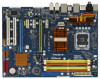
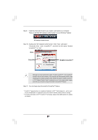
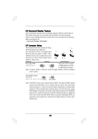
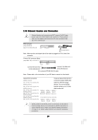
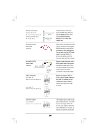
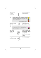
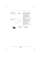
For Windows® VistaTM / VistaTM 64-bit OS: Click the right-top "Folder" icon , choose "Disable front panel jack detection", and save the change by clicking "OK". G. To activate the front mic. For Windows® 2000 / XP / XP 64-bit OS: Please select "Front Mic" as default record device. If you want to hear your voice through front mic, please deselect "Mute" icon in "Front Mic" of "Playback" portion. For Windows® VistaTM / VistaTM 64-bit OS: Go to the "Front Mic" Tab in the Realtek Control panel. Click "Set Default Device" to make the Front Mic as the default record device. System Panel Header (9-pin PANEL1) (see p.11, No. 24 or p.12 No. 23) Chassis Speaker Header (4-pin SPEAKER 1) (see p.11, No. 20 or p.12 No. 19) Chassis Fan Connector (3-pin CHA_FAN1) (see p.11, No. 16 or p.12 No. 15) PLED+ PLEDPWRBTN# GND 1 DUMMY RESET# GND HDLEDHDLED+ 1 SPEAKER DUMMY DUMMY +5V This header accommodates several system front panel functions. Please connect the chassis speaker to this header. Please connect a chassis fan cable to this connector and match the black wire to the ground pin. CPU Fan Connector (4-pin CPU_FAN1) (see p.11/12, No. 4) Please connect a CPU fan cable 1 GND 2 +12V to this connector and match 3 4 CPU_FAN_SPEED FAN_SPEED_CONTROL the black wire to the ground pin. Though this motherboard provides 4-Pin CPU fan (Quiet Fan) support, the 3-Pin CPU fan still can work successfully even without the fan speed control function. If you plan to connect the 3-Pin CPU fan to the CPU fan connector on this motherboard, please connect it to Pin 1-3. Pin 1-3 Connected 3-Pin Fan Installation 32
-
 1
1 -
2
-
3
-
4
-
5
-
6
-
7
-
8
-
9
-
10
-
11
-
12
-
13
-
14
-
15
-
16
-
17
-
18
-
19
-
20
-
21
-
22
-
23
-
24
-
25
-
26
-
 27
27 -
 28
28 -
 29
29 -
 30
30 -
 31
31 -
 32
32 -
 33
33 -
 34
34 -
 35
35 -
 36
36 -
 37
37 -
38
-
39
-
40
-
41
-
42
-
43
-
44
-
45
-
46
-
47
-
48
-
49
-
50
-
51
-
52
-
53
-
54
-
55
-
56
-
57
-
58
-
59
-
60
-
61
-
62
-
63
-
64
-
65
-
66
-
67
-
68
-
69
-
70
-
71
-
72
-
73
-
74
-
75
-
76
-
77
-
78
 |
 |