ASRock X58 Extreme6 User Manual
ASRock X58 Extreme6 Manual
 |
View all ASRock X58 Extreme6 manuals
Add to My Manuals
Save this manual to your list of manuals |
ASRock X58 Extreme6 manual content summary:
- ASRock X58 Extreme6 | User Manual - Page 1
X58 Extreme6 User Manual Version 1.0 Published August 2010 Copyright©2010 ASRock INC. All rights reserved. 1 - ASRock X58 Extreme6 | User Manual - Page 2
purchaser for backup purpose, without written consent of ASRock Inc. Products and corporate names appearing in this manual may or may not be registered trademarks or copyrights USA ONLY The Lithium battery adopted on this motherboard contains Perchlorate, a toxic substance controlled in Perchlorate - ASRock X58 Extreme6 | User Manual - Page 3
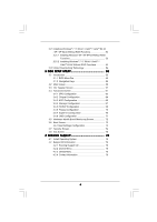
HDD Hot Plug Feature and Operation Guide 47 2.19 Driver Installation Guide 49 2.20 Installing Windows® 7 / 7 64-bit / VistaTM / VistaTM 64-bit / XP / XP 64-bit With RAID Functions 49 2.20.1 Installing Windows® XP / XP 64-bit With RAID Functions 49 2.20.2 Setting Up a "RAID Ready" System 50 2.20 - ASRock X58 Extreme6 | User Manual - Page 4
64-bit / XP / XP 64-bit Without RAID Functions 53 2.21.1 Installing Windows® XP / XP 64-bit Without RAID Functions 53 2.21.2 Installing Windows® 7 / 7 64-bit / VistaTM / VistaTM 64-bit Without RAID Functions 54 2.22 Untied Overclocking Technology 54 3 BIOS SETUP UTILITY 55 3.1 Introduction 55 - ASRock X58 Extreme6 | User Manual - Page 5
guide to BIOS setup and information of the Support CD. Because the motherboard specifications and the BIOS software might be updated, the content of this manual will be subject to change without notice. In case any modifications of this manual occur, the updated version will be available on ASRock - ASRock X58 Extreme6 | User Manual - Page 6
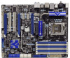
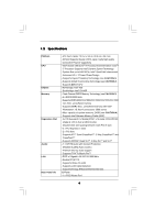
non-ECC, un-buffered memory - Supports DDR3 ECC, un-buffered memory with Intel® Workstation 1S Xeon® processors 3500 series - Max. capacity of system memory: 24GB (see CAUTION 4) - Supports Intel® Extreme Memory Profile (XMP) - 3 x PCI Express 2.0 x16 slots (PCIE1: x16 mode; PCIE4/PCIE5: single at - ASRock X58 Extreme6 | User Manual - Page 7
eSATA3 port) - 4 x Rear USB 3.0 ports by NEC UPD720200, support USB 1.0/2.0/3.0 up to 5Gb/s - 1 x Front USB 3.0 header (supports 2 USB 3.0 ports) by NEC UPD720200, supports USB 1.0/2.0/3.0 up to 5Gb/s - 6 x SATAII 3.0Gb/s connectors, support RAID (RAID 0, RAID 1, RAID 10, RAID 5 and Intel Matrix - ASRock X58 Extreme6 | User Manual - Page 8
Supports I. O. T. (Intelligent Overclocking Technology) Support CD - Drivers, Utilities, AntiVirus Software (Trial Version), ASRock ASRock Instant Flash (see CAUTION 8) - ASRock OC DNA (see CAUTION 9) - ASRock AIWI (see CAUTION 10) - ASRock 3V, CPU Vcore OS - Microsoft® Windows® 7 / 7 64-bit / - ASRock X58 Extreme6 | User Manual - Page 9
motherboard supports Untied Overclocking Technology. Please read "Untied Overclocking Technology" on page 54 for details. 3. This motherboard supports Triple Channel Memory Technology. Before you implement Triple Channel Memory Technology, make sure to read the installation guide of memory modules - ASRock X58 Extreme6 | User Manual - Page 10
CPU and the heatsink when you install the PC system. 14. Combo Cooler Option (C.C.O.) provides the flexible option to adopt two different CPU cooler types, Socket LGA 775 and LGA 1366. Please be noticed that not all the 775 CPU Fan can be used. 10 - ASRock X58 Extreme6 | User Manual - Page 11
for the completed system. According to EuP, the total AC power of the completed system shall be under 1.00W in off mode condition. To meet EuP standard, an EuP ready motherboard and an EuP ready power supply are required. According to Intel's suggestion, the EuP ready power supply must meet the - ASRock X58 Extreme6 | User Manual - Page 12
1 1 PCI1 RoHS PCI2 1394a NEC USB 3.0 Front USB 3.0 PCIE5 FLOPPY1 IR1 1 CHA_FAN1 FRONT_1394 1 X58 Extreme6 Intel ICH10R CMOS Battery Debug LED USB8_9 1 USB3_1_2 CLRCMOS1 1 SPEAKER1 1 8Mb BIOS PWRBTN PLED1 1 PLED PWRBTN PANEL1 RSTBTN 1 HDLED RESET 7 8 9 10 11 12 13 14 15 16 17 - ASRock X58 Extreme6 | User Manual - Page 13
(Orange) 8 Line In (Light Blue) ** 9 Front Speaker (Lime) 14 13 12 11 10 11 12 *** 13 14 15 16 17 18 Microphone (Pink) USB 3.0 Ports (USB67) IEEE 1394 Port (IEEE 1394) eSATA3 Connector USB 3.0 Ports (USB23) USB 2.0 Ports (USB01) Optical SPDIF Out Port Clear CMOS Switch (CLRCBTN) PS/2 Keyboard - ASRock X58 Extreme6 | User Manual - Page 14
Primary output" to use Rear Speaker, Central/Bass, and Front Speaker, or select "Realtek HDA Audio 2nd output" to use front panel audio. *** eSATA3 connector supports SATA 6Gb/s in cable 1M, supports SATA 3Gb/s in cable 2M. 14 - ASRock X58 Extreme6 | User Manual - Page 15
Precautions Take note of the following precautions before you install motherboard components or change any motherboard settings. 1. Unplug the power cord from the wall socket before touching any component. 2. To avoid damaging the motherboard components due to static electricity, NEVER place your - ASRock X58 Extreme6 | User Manual - Page 16
the installation of Intel 1366-Pin CPU, please follow the steps below. Load Plate Contact Array Socket Body Load Lever 1366-Pin Socket Overview Before you insert the 1366-Pin CPU into the socket, please check if cap. 2. This cap must be placed if returning the motherboard for after service. 16 - ASRock X58 Extreme6 | User Manual - Page 17
Heat Sink) up. Locate Pin1 and the two orientation key notches. orientation key notch Pin1 Pin1 alignment key orientation key notch 1366-Pin CPU alignment key 1366-Pin Socket For proper inserting, please ensure to match the two orientation key notches of the CPU with the two alignment keys of - ASRock X58 Extreme6 | User Manual - Page 18
with fan operation or contact other components. Please be noticed that this motherboard supports Combo Cooler Option (C.C.O.), which provides the flexible option to adopt two different CPU cooler types, Socket LGA 775 and LGA 1366. The white throughholes are for Socket LGA 1366 CPU fan. 18 - ASRock X58 Extreme6 | User Manual - Page 19
only one DIMM is installed into DDR3_A2, DDR3_B2 or DDR3_C2 slot. 3. Due to Intel® CPU spec definition, XMP DIMMs and DDR3 2000/ 1866/1600 are supported for one DIMM per channel only. 4. You may install varying memory sizes in Channel A, Channel B and Channel C. The system maps the total size of the - ASRock X58 Extreme6 | User Manual - Page 20
matches the break on the slot. notch break notch break The DIMM only fits in one correct orientation. It will cause permanent damage to the motherboard and the DIMM if you force the DIMM into the slot at incorrect orientation. Step 3. Firmly insert the DIMM into the slot until the retaining - ASRock X58 Extreme6 | User Manual - Page 21
to install PCI Express graphics cards to support 3-Way CrossFireXTM or 3-Way SLITM function. 1. In single VGA card mode, it is recommended to install a PCI the installation. Step 2. Remove the system unit cover (if your motherboard is already installed in a chassis). Step 3. Remove the bracket facing - ASRock X58 Extreme6 | User Manual - Page 22
, 3-Way SLITM and Quad SLITM Operation Guide This motherboard supports NVIDIA® SLITM, 3-Way SLITM and Quad SLITM (Scalable Link Interface) technology that allows you to install up to three identical PCI Express x16 graphics cards. Currently, NVIDIA® SLITM technology supports Windows® XP / XP 64-bit - ASRock X58 Extreme6 | User Manual - Page 23
Step3. Align and insert ASRock SLI_Bridge_2S Card to the goldfingers on each graphics card. Make sure ASRock SLI_Bridge_2S Card is firmly in place. ASRock SLI_Bridge_2S Card Step4. Connect a VGA cable or a DVI cable to the monitor connector or the DVI connector of the graphics card that is inserted - ASRock X58 Extreme6 | User Manual - Page 24
connected. Repeat this step on the three graphics cards. Step3. Align and insert ASRock 3-Way SLI-2S2S Bridge Card to the goldfingers on each graphics card. Make sure ASRock 3-Way SLI-2S2S Bridge Card is firmly in place. ASRock 3-Way SLI-2S2S Bridge Card Step4. Connect a VGA cable or a DVI cable - ASRock X58 Extreme6 | User Manual - Page 25
the graphics card drivers to your system. After that, you can enable the MultiGraphics Processing Unit (GPU) feature in the NVIDIA® nView system tray utility. Please follow the below procedures to enable the multi-GPU feature. For Windows® XP / XP 64-bit OS: (For SLITM mode only) A. Double-click - ASRock X58 Extreme6 | User Manual - Page 26
® VistaTM / VistaTM 64-bit / 7 / 7 64-bit OS: (For SLITM and Quad SLITM mode) A. Click the Start icon on your Windows taskbar. B. From the pop-up menu, select All Programs, and then click NVIDIA Corporation. C. Select NVIDIA Control Panel tab. D. Select Control Panel tab. E. From the - ASRock X58 Extreme6 | User Manual - Page 27
For Windows® VistaTM / VistaTM 64-bit / 7 / 7 64-bit OS: (For 3-Way SLITM mode) A. Follow step A to D on page 26. B. From the pop-up menu, select Set SLI and PhysX configuration. In Select a hardware acceleration setting for PhysX item, - ASRock X58 Extreme6 | User Manual - Page 28
Currently CrossFireXTM feature is supported with Windows® XP with Service Pack 2 / VistaTM / 7 OS. 3-way CrossFireXTM and Quad CrossFireXTM feature are supported with Windows® VistaTM / 7 OS only. Please check AMD website for ATITM CrossFireXTM driver updates. 1. If a customer incorrectly configures - ASRock X58 Extreme6 | User Manual - Page 29
Bridge Interconnects on the top of Radeon graphics cards. (CrossFire Bridge is provided with the graphics card you purchase, not bundled with this motherboard. Please refer to your graphics card vendor for details.) CrossFire Bridge or Step 3. Connect the DVI monitor cable to the DVI connector - ASRock X58 Extreme6 | User Manual - Page 30
Bridge to connect Radeon graphics cards on PCIE4 and PCIE5 slots. (CrossFireTM Bridge is provided with the graphics card you purchase, not bundled with this motherboard. Please refer to your graphics card vendor for details.) 30 - ASRock X58 Extreme6 | User Manual - Page 31
CrossFireTM Bridge Step 5. Connect the DVI monitor cable to the DVI connector on the Radeon graphics card on PCIE1 slot. (You may use the DVI to D-Sub adapter to convert the DVI connector to D-Sub interface, and then connect the D-Sub monitor cable to the DVI to D-Sub adapter.) 31 - ASRock X58 Extreme6 | User Manual - Page 32
to installation. Please check AMD website for ATITM driver updates. Step 3. Step 4. Step 5. Install the required drivers to your system. For Windows® XP OS: A. ATITM recommends Windows® XP Service Pack 2 or higher to be installed (If you have Windows® XP Service Pack 2 or higher installed in your - ASRock X58 Extreme6 | User Manual - Page 33
for identification or explanation and to the owners' benefit, without intent to infringe. * For further information of ATITM CrossFireXTM technology, please check AMD website for updates and details. 33 - ASRock X58 Extreme6 | User Manual - Page 34
motherboard supports Surround Display upgrade. With the external add-on PCI Express VGA cards, you can easily enjoy the benefits of Surround Display feature. For the detailed instruction, please refer to the document at the following path in the Support CD: ..\ Surround Display Information 2.10 - ASRock X58 Extreme6 | User Manual - Page 35
end to the motherboard connect the black end to the IDE devices 80-conductor ATA 66/100/133 cable Note: Please refer to the instruction of your IDE 10) (SATA3_3_4: see p.12, No. 11) (SATA3_5_6: see p.12, No. 12) SATA3_5_6 SATA3_3_4 SAT3_1_2 These six Serial ATA3 (SATA3) connectors support - ASRock X58 Extreme6 | User Manual - Page 36
, there is one USB 2.0 header on this motherboard. This USB 2.0 header can support two USB 2.0 ports. Besides four default USB 3.0 ports on the I/O panel, there is one USB 3.0 header on this motherboard. This USB 3.0 header can support two USB 3.0 ports. This header supports an optional wireless - ASRock X58 Extreme6 | User Manual - Page 37
supports Jack Sensing, but the panel wire on the chassis must support HDA to function correctly. Please follow the instruction in our manual and chassis manual activate the front mic. For Windows® XP / XP 64-bit OS: Select "Mixer". Select "Recorder". Then click "FrontMic". For Windows® 7 / 7 64-bit - ASRock X58 Extreme6 | User Manual - Page 38
HDLED (Hard Drive Activity LED): Connect to the hard drive activity LED on the chassis front panel. The LED is on when the hard drive is reading or writing data. The front panel design may differ by chassis. A front panel module mainly consists of power switch, reset switch, power LED, hard drive - ASRock X58 Extreme6 | User Manual - Page 39
provides 4-Pin CPU fan (Quiet Fan) support, the 3-Pin CPU fan still can work successfully even without the fan speed control function. If you plan to connect the 3-Pin CPU fan to the CPU fan connector on this motherboard, please connect it to Pin 1-3. Pin 1-3 Connected 3-Pin Fan Installation - ASRock X58 Extreme6 | User Manual - Page 40
COM1 header supports a serial port module. HDMI_SPDIF header, providing SPDIF audio output to HDMI VGA card, allows the system to connect HDMI Digital TV/ projector/LCD devices. Please connect the HDMI_SPDIF connector of HDMI VGA card to this header. The Installation Guide of Front USB 3.0 Panel - ASRock X58 Extreme6 | User Manual - Page 41
the two screws from the Front USB Step 2 Put the USB 3.0 cable and the rear USB 3.0 3.0 Panel. bracket together. Step 3 Screw the two screws into the rear USB 3.0 bracket. Step 4 Put the rear USB 3.0 bracket into the chassis. 2.12 Smart Switches The motherboard has three smart switches: power - ASRock X58 Extreme6 | User Manual - Page 42
additional chipset initialization. Re-enable CACHE. Verify that flat mode is enabled. Test base 512KB memory. Adjust policies and cache first 8MB. Set stack. Bootblock code is copied from ROM to lower system memory and control is given to it. BIOS now executes out of RAM. Both key sequence and OEM - ASRock X58 Extreme6 | User Manual - Page 43
BIOS modules on POST entry and GPNV area. Initialized CMOS as mentioned in the Kernel Variable "wCMOSFlags." Check CMOS diagnostic byte to determine if battery power is OK and CMOS checksum is OK. Verify CMOS checksum manually by reading storage area. If the CMOS checksum is bad, update test memory - ASRock X58 Extreme6 | User Manual - Page 44
needed. 52 Updates CMOS memory size from memory found in memory test. Allocates memory for Extended BIOS Data Area from base memory. 60 Initializes 87 Execute BIOS setup if needed / requested. 8C Late POST initialization of chipset registers. 8D Build ACPI tables (if ACPI is supported) 8E - ASRock X58 Extreme6 | User Manual - Page 45
south bridge chipset that supports Serial ATA (SATA) / Serial ATAII (SATAII) hard disks and RAID (RAID 0, RAID 1, RAID 10, RAID 5, and Intel Matrix Storage) functions. You may install SATA / SATAII hard disks on this motherboard for internal storage devices. This section will guide you to install - ASRock X58 Extreme6 | User Manual - Page 46
while the system is still power-on and in working condition. 2.17 Hot Plug and Hot Swap Functions for SATA3 HDDs This motherboard supports Hot Plug and Hot Swap functions for SATA3_1 and SATA3_2 in RAID / AHCI mode. It also supports Hot Plug function for SATA3_3, SATA3_4, SATA3_5 and SATA3_6 in AHCI - ASRock X58 Extreme6 | User Manual - Page 47
2.18 SATA / SATAII / SATA3 HDD Hot Plug Feature and Operation Guide This motherboard supports Hot Plug feature for SATA / SATAII / SATA3 HDD in RAID / AHCI mode. Please read below operation guide of Hot Plug feature carefully. Before you process the SATA / SATAII / SATA3 HDD Hot Plug, please check - ASRock X58 Extreme6 | User Manual - Page 48
cable to (White) to the power supply 1x4-pin cable. the motherboard's SATAII / SATA3 connector. SATA power cable 1x4-pin power connector ( of attention, before you process the Hot Unplug: Please do follow below instruction sequence to process the Hot Unplug, improper procedure will cause the SATA - ASRock X58 Extreme6 | User Manual - Page 49
the floppy diskette and copy SATA / SATAII drivers into the floppy diskette. STEP 3: Use "RAID Installation Guide" to set RAID configuration. Before you start to configure the RAID function, you need to check the installation guide in the Support CD for proper configuration. Please refer to the - ASRock X58 Extreme6 | User Manual - Page 50
your system. After making a SATA / SATAII driver diskette and using "RAID Installation Guide" to set RAID configuration, you can start to install Windows® XP / XP 64-bit on your system. At the beginning of Windows setup, press F6 to install a third-party RAID driver. When prompted, insert the SATA - ASRock X58 Extreme6 | User Manual - Page 51
motherboard or after downloading it from the Internet. This will add the Intel(R) Matrix Storage Console which can be used to manage the RAID configuration. 7. After setting up a "RAID . If you migrated to a RAID 0 volume, use Disk Management from within Windows® in order to partition and format - ASRock X58 Extreme6 | User Manual - Page 52
CD for proper configuration. Please refer to the document in the Support CD, "Guide to SATA Hard Disks Installation and RAID Configuration", which is located in the folder at the following path: .. \ RAID Installation Guide STEP 3: Install Windows® 7 / 7 64-bit / VistaTM / VistaTM 64-bit OS on your - ASRock X58 Extreme6 | User Manual - Page 53
® XP / XP 64-bit Without RAID Functions If you want to install Windows® XP / XP 64-bit OS on your SATA / SATAII HDDs without RAID functions, please follow below steps. Using SATA / SATAII HDDs with NCQ function STEP 1: Set Up BIOS. A. Enter BIOS SETUP UTILITY Advanced screen Storage Configuration - ASRock X58 Extreme6 | User Manual - Page 54
Technology This motherboard supports Untied Overclocking Technology, which means during overclocking, FSB enjoys better margin due to fixed PCI / PCIE buses. Before you enable Untied Overclocking function, please enter "Overclock Mode" option of BIOS setup to set the selection from [Auto] to [Manual - ASRock X58 Extreme6 | User Manual - Page 55
BIOS FWH chip on the motherboard stores the BIOS SETUP UTILITY. You may run the BIOS SETUP UTILITY when you start up the computer. Please press or during the Power-On-Self-Test (POST) to enter the BIOS To set up overclocking features Advanced To set up the advanced BIOS features H/W - ASRock X58 Extreme6 | User Manual - Page 56
08/03/2010] BIOS Version : X58 Extreme6 P1.00 Processor Type : Intel (R) Core (TM) i7 CPU 975 @ 3.33GHz (64bit) Processor Speed : 3333MHz Microcode Update : 106A5/11 Cache Size : 8192KB Total Memory DDR3_A2 DDR3_A1 DDR3_B2 DDR3_B1 DDR3_C2 DDR3_C1 : 2048MB Single-Channel Memory Mode : None - ASRock X58 Extreme6 | User Manual - Page 57
to your memory and motherboard. It should be done at your own risk and expense. XMP Frequency Use this option to adjust XMP frequency. Configuration options: [Auto] and [Profile 1]. The default value is [Auto]. Overclock Mode Use this to select Overclock Mode. Configuration options: [Auto], [Manual - ASRock X58 Extreme6 | User Manual - Page 58
, the motherboard will detect the memory module(s) inserted and assigns appropriate frequency automatically. You may select [Auto], [400MHz DDR3_800], [533MHz DDR3_1066], [666MHz DDR3_1333], [800MHz DDR3_1600], [933MHz DDR3_1866] or [1066MHz DDR3_2133]. DRAM Timing Control BIOS - ASRock X58 Extreme6 | User Manual - Page 59
clocks for TWTR. Configuration options: Configuration options: [Auto], [2] to [10]. DRAM tRRD This controls the number of DRAM clocks for TRRD. BIOS option, you can also choose our Intelligent Energy Saver utility to enable this function. ASRock VDroop Control Use this to enable or disable ASRock - ASRock X58 Extreme6 | User Manual - Page 60
CPU Voltage Use this to select CPU Voltage. Configuration options: [Auto], [Manual] and [Overdrive Offset]. The default value is [Auto]. DRAM Voltage Use this to select DRAM Voltage. The default value is [Auto]. IOH Voltage Use this - ASRock X58 Extreme6 | User Manual - Page 61
malfunction. ASRock Instant Flash ASRock Instant Flash is a BIOS flash utility embedded in Flash ROM. This convenient BIOS update tool allows you to update system BIOS without entering operating systems first like MS-DOS or Windows®. Just launch this tool and save the new BIOS file to your USB flash - ASRock X58 Extreme6 | User Manual - Page 62
BIOS Throttling No-Excute Memory Protection Intel (R) HT Technology Active Processor Cores A20M Intel motherboard. Enhance Halt State (C1E) All processors support the Halt State (C1). The C1 state is supported through the native processor instructions HLT and MWAIT and requires no hardware support - ASRock X58 Extreme6 | User Manual - Page 63
Windows® VistaTM / 7 and want to enable this function, please set this item to [Enabled]. This item will be hidden if the current CPU does not support above issue occurs. Intel (R) TurboMode tech Use this item to enable or disable Intel (R) Turbo Boost Technology. Turbo mode allows processor cores - ASRock X58 Extreme6 | User Manual - Page 64
default value is [Auto]. 3.4.2 Chipset Configuration Advanced Chipset Settings BIOS SETUP UTILITY Primary Graphics Adapter Onboard HD Audio Front Panel the maximum TLP (Transaction Layer Packet) payload size that can be supported by PCI Express controller. Configuration options: [128B] and [256B - ASRock X58 Extreme6 | User Manual - Page 65
Good Night LED Enable this option to turn off Power LED, Lan LED and Port80 LED when the system is power on. The keyboard LED will also be turned off in S1, S3 and S4 state. The default value is [Disabled]. Port80 LED after POST Enable or disable Port80 LED after POST. The default value is [Enabled - ASRock X58 Extreme6 | User Manual - Page 66
BIOS feature. Select [Auto] will enable this feature if the OS supports it. Check Ready Bit Use this item to enable or disable turn on the system from the power-soft-off mode. PCI Devices Power On Use this item to enable or disable motherboard to submit Windows® VistaTM certification. 66 - ASRock X58 Extreme6 | User Manual - Page 67
you are allowed to set the selection to [IDE], [RAID] or [AHCI]. The default value is [IDE]. If you select [RAID] or [AHCI] mode, the options "Hot Plug" and "SATA Link Power Management" will appear. AHCI (Advanced Host Controller Interface) supports NCQ and other new features that will improve SATA - ASRock X58 Extreme6 | User Manual - Page 68
following instruction. BIOS SETUP UTILITY Advanced SATAII 1 Master Device Vendor Size LBA Mode Block Mode PIO Mode Async DMA Ultra DMA S.M.A.R.T. Type LBA/Large Mode Block (Multi-Sector Transfer) PIO Mode DMA Mode S.M.A.R.T. 32Bit Data Transfer :Hard Disk :ST340014A :40.0 GB :Supported :16Sectors - ASRock X58 Extreme6 | User Manual - Page 69
rate. AHCI CD/DVD Boot Time Out Some SATA CD / DVD in AHCI mode need to wait ready longer. Configuration options: [0], [5], [10], [15], [20], [25], [30] and [35]. The default value is [35]. 3.4.5PCIPnP Configuration BIOS SETUP UTILITY Advanced Advanced PCI / PnP Settings PCI Latency Timer PCI IDE - ASRock X58 Extreme6 | User Manual - Page 70
SETUP UTILITY Advanced Configure Super IO Chipset OnBoard Floppy Controller Serial Port Address Infrared Port Address [Enabled] [3F8 / IRQ4] [Disabled] Allow BIOS to Enable or Disable Floppy Controller. +F1 F9 F10 ESC Select Screen Select Item Change Option General Help Load Defaults Save and - ASRock X58 Extreme6 | User Manual - Page 71
3.4.8 USB Configuration BIOS SETUP UTILITY Advanced USB Configuration USB Controller USB 2.0 Support Legacy USB Support USB Keyboard/Remote Power On USB Mouse Power On Onboard USB3 Controller [Enabled] [Enabled] [Enabled] [Disabled] [Disabled] [Enabled] To enable or disable the onboard USB - ASRock X58 Extreme6 | User Manual - Page 72
of the CPU temperature, motherboard temperature, CPU fan speed, chassis fan speed, and the critical voltage. BIOS SETUP UTILITY Main OC set the chassis fan1 speed. Configuration options: [Full On], [Automatic mode] and [Manual Mode]. The default is value [Full On]. Chassis Fan2 Setting This allows - ASRock X58 Extreme6 | User Manual - Page 73
F1 General Help F9 Load Defaults F10 Save and Exit ESC Exit v02.54 (C) Copyright 1985-2005, American Megatrends, Inc. 3.6.1 Boot Settings Configuration BIOS SETUP UTILITY Boot Boot Settings Configuration Full Screen Logo AddOn ROM Display Boot Logo Boot From Onboard LAN Bootup Num-Lock [Enabled - ASRock X58 Extreme6 | User Manual - Page 74
option "Full Screen Logo". Configuration options: [Auto], [EuP], [Scenery] and [ASRock X58]. The default value is [Auto]. Boot From Onboard LAN Use this item to system. For the user password, you may also clear it. BIOS SETUP UTILITY Main OC Tweaker Advanced H/W Monitor Boot Security Exit Security - ASRock X58 Extreme6 | User Manual - Page 75
Exit Exit Options Save Changes and Exit Discard Changes and Exit Discard Changes Load BIOS Defaults Load Performance Setup Default (IDE/SATA) Load Performance Setup AHCI Mode Load Performance Setup RAID Mode Load Power Saving Setup Default Exit system setup after saving the changes. F10 key - ASRock X58 Extreme6 | User Manual - Page 76
install the necessary drivers to activate the devices. 4.2.3 Utilities Menu The Utilities Menu shows the applications software that the motherboard supports. Click on a specific item then follow the installation wizard to install it. 4.2.4 Contact Information If you need to contact ASRock or want to
-
 1
1 -
 2
2 -
 3
3 -
 4
4 -
 5
5 -
 6
6 -
 7
7 -
8
-
9
-
10
-
11
-
12
-
13
-
14
-
15
-
16
-
17
-
18
-
19
-
20
-
21
-
22
-
23
-
24
-
25
-
26
-
27
-
28
-
29
-
30
-
31
-
32
-
33
-
34
-
35
-
36
-
37
-
38
-
39
-
40
-
41
-
42
-
43
-
44
-
45
-
46
-
47
-
48
-
49
-
50
-
51
-
52
-
53
-
54
-
55
-
56
-
57
-
58
-
59
-
60
-
61
-
62
-
63
-
64
-
65
-
66
-
67
-
68
-
69
-
70
-
71
-
72
-
73
-
74
-
75
-
76
 |
 |

1
X58 Extreme6
User Manual
Version 1.0
Published August 2010
Copyright©2010 ASRock INC. All rights reserved.