ASRock X79 Extreme6 User Manual
ASRock X79 Extreme6 Manual
 |
View all ASRock X79 Extreme6 manuals
Add to My Manuals
Save this manual to your list of manuals |
ASRock X79 Extreme6 manual content summary:
- ASRock X79 Extreme6 | User Manual - Page 1
X79 Extreme6/GB X79 Extreme6 User Manual Version 1.0 Published December 2011 Copyright©2011 ASRock INC. All rights reserved. 1 - ASRock X79 Extreme6 | User Manual - Page 2
commitment by ASRock. ASRock assumes no responsibility for any errors or omissions that may appear in this manual. With respect to the contents of this manual, ASRock does not , USA ONLY The Lithium battery adopted on this motherboard contains Perchlorate, a toxic substance controlled in Perchlorate - ASRock X79 Extreme6 | User Manual - Page 3
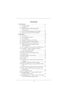
Screw Holes 18 2.2 Pre-installation Precautions 18 2.3 CPU Installation 19 2.4 Installation of Heatsink and CPU fan 21 2.5 Installation of Memory Modules (DIMM 22 2.6 Expansion Slots (PCI and PCI Express Slots 24 2.7 ASRock Game Blaster Installation Guide (X79 Extreme6/GB 25 2.8 SLITM, 3-Way - ASRock X79 Extreme6 | User Manual - Page 4
® XP / XP 64-bit Without RAID Functions 67 2.23.2 Installing Windows® 7 / 7 64-bit / VistaTM / VistaTM 64-bit Without RAID Functions 68 2.24 Teaming Function Operation Guide (X79 Extreme6/GB 69 2.25 Untied Overclocking Technology 72 3 UEFI SETUP UTILITY 73 3.1 Introduction 73 3.1.1 UEFI Menu - ASRock X79 Extreme6 | User Manual - Page 5
Installation Guide ASRock X79 Extreme6/GB / X79 Extreme6 Support CD 5 x Serial ATA (SATA) Data Cables (Optional) 1 x I/O Panel Shield 1 x Front USB 3.0 Panel 4 x HDD Screws 6 x Chassis Screws 1 x Rear USB 3.0 Bracket 1 x ASRock SLI_Bridge_2S Card 1 x ASRock 3-Way SLI-2S1S Bridge Card 1 x ASRock Game - ASRock X79 Extreme6 | User Manual - Page 6
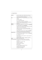
CPU - Supports Intel® CoreTM i7 processor family for the LGA 2011 Socket - Digi Power Design - 12 + 2 Power Phase Design - Supports Intel® Turbo Boost 2.0 Technology - Supports Hyper-Threading Technology (see CAUTION 1) - Supports Untied Overclocking Technology Chipset - Intel® X79 Memory - ASRock X79 Extreme6 | User Manual - Page 7
USB 3.0 Ports - 1 x RJ-45 LAN Port with LED (ACT/LINK LED and SPEED LED) - 1 x IEEE 1394 Port - 1 x Clear CMOS Switch with LED - HD Audio Jack: Side Speaker/Rear Speaker/Central/Bass/ Line in/Front Speaker/Microphone (see CAUTION 6) - 2 x SATA3 6.0 Gb/s connectors by Intel® X79, support RAID (RAID - ASRock X79 Extreme6 | User Manual - Page 8
(supports 2 USB 3.0 ports) - 1 x Dr. Debug with LED - 1 x Clear CMOS Switch with LED - 1 x Power Switch with LED - 1 x Reset Switch with LED - 64Mb AMI UEFI Legal BIOS with GUI support - Supports "Plug and Play" - ACPI 1.1 Compliance Wake Up Events - Supports jumperfree - SMBIOS 2.3.1 Support - CPU - ASRock X79 Extreme6 | User Manual - Page 9
is no such limitation. You can use ASRock XFast RAM to utilize the memory that Windows® cannot use. 5. Currently Intel® Socket 2011 Sandy Bridge-E Processor doesn't support PCIE 3.0, but this motherboard is already PCIE 3.0 hardware ready. It depends on Intel's CPU to enable PCIE 3.0. Please check - ASRock X79 Extreme6 | User Manual - Page 10
-DOS or Windows®. With this utility, you can press the key during the POST or the key to enter into the BIOS setup menu to access ASRock Instant Flash. Just launch this tool and save the new BIOS file to your USB flash drive, floppy disk or hard drive, then you can update your BIOS only in - ASRock X79 Extreme6 | User Manual - Page 11
improve heat dissipation, remember to spray thermal grease between the CPU and the heatsink when you install the PC system. 18. Intel Rapid Storage Technology enterprise 3.0, ASRock XFast RAM and ASRock Game Blaster are not supported by Microsoft® Windows® XP / XP 64-bit. 19. EuP stands for Energy - ASRock X79 Extreme6 | User Manual - Page 12
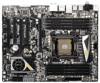
LED Header (PLED1) 6 ATX 12V Power Connector (ATX12V1) 31 Dr. Debug 7 2011-Pin CPU Socket 32 Chassis Fan Connector (CHA_FAN3) 8 CPU Fan Connector (CPU_FAN2) 33 Clear CMOS Jumper (CLRCMOS1) 9 CPU Fan Connector (CPU_FAN1) 34 USB 2.0 Header (USB_8_9, Black) 10 240-pin DDR3 DIMM Slot (DDR3_D2 - ASRock X79 Extreme6 | User Manual - Page 13
X79 Extreme6/GB / X79 Extreme6) 1 PS/2 Mouse Port (Green) 2 Coaxial SPDIF Out Port * 3 LAN RJ-45 Port 4 USB USB 2.0 Ports (USB01) USB 3.0 Ports (USB_23) USB 3.0 Ports (USB_01) Optical SPDIF Out Port Clear CMOS you use. TABLE for Audio Output Connection Audio Output Channels Front Speaker Rear - ASRock X79 Extreme6 | User Manual - Page 14
Multi-Streaming function, you need to connect a front panel audio cable to the front panel audio header. After restarting your computer, you will find "Mixer Front Speaker, or select "Realtek HDA Audio 2nd output" to use front panel audio. *** eSATA3 connector supports SATA Gen3 in cable 1M. 14 - ASRock X79 Extreme6 | User Manual - Page 15
1.5 ASRock Game Blaster (X79 Extreme6/GB) ASRock Game Blaster is packed with the new earthshattering Creative Sound Core3D quad-core sound and voice processor. It is designed to deliver sound and voice with unbeatable quality and accurate 3D positional audio. It also boosts gaming performance, - ASRock X79 Extreme6 | User Manual - Page 16
Header (3-pin HDMI_SPDIF1) DUMMY GND 1 SPDIF OUT **** The onboard audio will be disabled when ASRock Game Blaster is installed, but you can still enable it in the UEFI setup. If ASRock Game Blaster is installed, THX TruStudioTM function of the onboard audio Realtek ALC898 is not supported. 16 - ASRock X79 Extreme6 | User Manual - Page 17
PRO - Supports CrystalVoice - Supports EAX1.0 to EAX5.0 - Supports Full Blu-ray Profile 2.0 Audio Decoder - Supports Blu-ray Audio - Supports AES-128 Encryption/Decryption Engine - Broadcom BCM57781 - PCIE x1 Gigabit LAN 10/100/1000 Mb/s - Supports Wake-On-LAN - Supports Energy Efficient Ethernet 802 - ASRock X79 Extreme6 | User Manual - Page 18
. Do not over-tighten the screws! Doing so may damage the motherboard. 2.2 Pre-installation Precautions Take note of the following precautions before you install motherboard components or change any motherboard settings. 1. Unplug the power cord from the wall socket before touching any components - ASRock X79 Extreme6 | User Manual - Page 19
2.3 CPU Installation For the installation of Intel 2011-Pin CPU, please follow the steps below. Load Lever Load Plate Load Lever Contact Array Socket Body 2011-Pin Socket Overview Before you insert the 2011-Pin CPU into the socket, please check if the CPU surface is unclean or if there are any - ASRock X79 Extreme6 | User Manual - Page 20
Verify that the CPU is within the socket and properly mated to the orient keys. Step 3. Close the socket: Step 3-1. Flip the load plate onto the IHS, then the cover will automatically come off by itself. The cover must be placed if returning the motherboard for after service. Step 3-2. Press down - ASRock X79 Extreme6 | User Manual - Page 21
Heatsink This motherboard is equipped with 2011-Pin socket that supports Intel 2011-Pin CPU. Please adopt the type of heatsink and cooling fan compliant with Intel 2011Pin CPU to dissipate heat. Before you installed the heatsink, you need to spray thermal interface material between the CPU and the - ASRock X79 Extreme6 | User Manual - Page 22
and supports Quad Channel Memory Technology. For quad channel configuration, you always need to install identical (the same brand, speed, size and chip-type) DDR3 DIMM in the slots, so that Quad Channel Memory Technology can be activated. 1. Due to Intel® CPU spec definition, please install the memory - ASRock X79 Extreme6 | User Manual - Page 23
Installing a DIMM Please make sure to disconnect power supply before adding or removing break notch break The DIMM only fits in one correct orientation. It will cause permanent damage to the motherboard and the DIMM if you force the DIMM into the slot at incorrect orientation. Step 3. Firmly insert - ASRock X79 Extreme6 | User Manual - Page 24
. 6. Currently Intel® Socket 2011 Sandy Bridge-E Processor doesn't support PCIE 3.0, but this motherboard is already PCIE 3.0 hardware ready. It depends on Intel's CPU to enable PCIE 3.0. Please check Intel's website for information on future CPU updates and releases. Installing an expansion card - ASRock X79 Extreme6 | User Manual - Page 25
card to the chassis with screws. Replace the system cover. 2.7 ASRock Game Blaster Installation Guide (X79 Extreme6/GB) 2.7.1 ASRock Game Blaster and Driver Installation Step 1. Please refer to the "Expansion Slots" section then insert ASRock Game Blaster into PCIE4 slot. Step 2. In order to avoid - ASRock X79 Extreme6 | User Manual - Page 26
Step 3. Follow the step by step driver setup directions. Please make sure to use Windows® VistaTM 32-bit / 64-bit or Windows® 7 32-bit / 64-bit. ASRock Game Blaster is not supported under Windows® XP / XP 64-bit. Step 4. Restart your computer for ASRock Game Blaster to take effect. 26 - ASRock X79 Extreme6 | User Manual - Page 27
you to follow the steps below to uninstall the chassis of the ASRock Game Blaster to fix the conflict. Step 1. Unscrew the four screws which hold the chassis and ASRock Game Blaster together. Step 2. Remove the chassis of the ASRock Game Blaster. Step 3. Refasten the screw on the upper left corner and - ASRock X79 Extreme6 | User Manual - Page 28
2.7.2 ASRock Game Blaster Configuration This section explains how to configure your ASRock Game Blaster. 2.7.2.1 THX TRUSTUDIO PRO THX TruStudio Pro Click the power button on the left to activate or deactivate. Surround Control the level of audio immersion in music, movies and games. Crystalizer - ASRock X79 Extreme6 | User Manual - Page 29
power button on the left to activate or deactivate. FX Morph your voice into different characters and accents. Smart Volume Be heard clearly without having to shout or whisper. Noise Reduction Eliminate unwanted background noise in your conversation. Acoustic Echo Cancellation Eliminate echoes that - ASRock X79 Extreme6 | User Manual - Page 30
or disable rear pair speakers. If there are both speakers and front headphones connected, please select the device you desire to use as audio output. Full-Range Speakers: Select full-range speakers. Front left and right Surround speakers Bass Management Bass Redirection Enable or disable bass - ASRock X79 Extreme6 | User Manual - Page 31
2.7.2.4 MIXER Playback Speakers Control the level of speakers playback. SPDIF-Out Control the level of SPDIF-Out playback. Balance Control the level of various speaker's balance. REC Input Device Select input device. What U Hear Control the level of playback redirect. 31 - ASRock X79 Extreme6 | User Manual - Page 32
2.7.2.5 EQUALIZER EQ Choose from Flat, Acoustic, Classical, Country, Dance, Jazz, New Age, Pop, Rock and Vocal. 2.7.2.6 JACK SETUP 32 - ASRock X79 Extreme6 | User Manual - Page 33
Speakers Side Speakers Front panel headphones is shared with side speakers. Stereo and Microphone Speakers Microphone Stereo and Line-In Speakers Line-In Show Jack Setup dialog when an audio jack is inserted Enable or disable Jack - ASRock X79 Extreme6 | User Manual - Page 34
2.7.2.7 ADVANCED FEATURES Play stereo mix to digital output Enable or disable play stereo mix to digital output. 34 - ASRock X79 Extreme6 | User Manual - Page 35
2.7.2.8 PROFILE User Profiles You can save, load or delete your user profiles. The default is . 35 - ASRock X79 Extreme6 | User Manual - Page 36
you want to hear your own voice through the microphone (Playback mode). You can enable it by using ASRock Game Blaster's configuration Utility CRYSTALVOICE Test. OR you can change your settings to "playback mode" by checking the "Listen to this device" box in Control panel Sound Recording Microphone - ASRock X79 Extreme6 | User Manual - Page 37
, 3-Way SLITM and Quad SLITM Operation Guide This motherboard supports NVIDIA® SLITM, 3-Way SLITM and Quad SLITM (Scalable Link Interface) technology that allows you to install up to three identical PCI Express x16 graphics cards. Currently, NVIDIA® SLITM technology supports Windows® XP / XP 64-bit - ASRock X79 Extreme6 | User Manual - Page 38
Step3. Align and insert the ASRock SLI_Bridge_2S Card to the goldfingers on each graphics card. Make sure the ASRock SLI_Bridge_2S Card is firmly in place. ASRock SLI_Bridge_2S Card Step4. Connect a VGA cable or a DVI cable to the monitor connector or the DVI connector of the graphics card that is - ASRock X79 Extreme6 | User Manual - Page 39
Graphics Cards Step 1. Install the identical 3-Way SLITM-ready graphics cards that are NVIDIA® certified because different types of graphics cards will not work together properly. (Even the GPU chips version shall be the same.) Each graphics card should have two goldfingers for ASRock 3-Way SLI-2S1S - ASRock X79 Extreme6 | User Manual - Page 40
2.8.2 Driver Installation and Setup Install the graphics card drivers to your system. After that, you can enable the MultiGraphics Processing Unit (GPU) feature in the NVIDIA® nView system tray utility. Please follow the below procedures to enable the multi-GPU feature. For Windows® XP / XP 64-bit - ASRock X79 Extreme6 | User Manual - Page 41
OS: (For SLITM and Quad SLITM mode) A. Click the Start icon on your Windows taskbar. B. From the pop-up menu, select All Programs, and then click NVIDIA Panel tab. E. From the pop-up menu, select Set SLI and PhysX configuration. In Set PhysX GPU acceleration item, please select Enabled. In Select - ASRock X79 Extreme6 | User Manual - Page 42
For Windows® VistaTM / VistaTM 64-bit / 7 / 7 64-bit OS: (For 3-Way SLITM mode) A. Follow steps A to D on page 41. B. From the pop-up menu, select Set SLI and PhysX configuration. In Select a hardware acceleration setting for PhysX item, please select Enabled. In Select an SLI configuration item, - ASRock X79 Extreme6 | User Manual - Page 43
supported with Windows® XP with Service Pack 2 / VistaTM / 7 OS. 3-way CrossFireXTM and Quad CrossFireXTM feature are supported with Windows® VistaTM / 7 OS only. Please check AMD website for ATITM CrossFireXTM driver updates Setup 2.9.1.1 Installing card manuals for detailed installation guide. Step - ASRock X79 Extreme6 | User Manual - Page 44
Step 2. Connect two Radeon graphics cards by installing CrossFire Bridge on CrossFire Bridge Interconnects on the top of Radeon graphics cards. (CrossFire Bridge is provided with the graphics card you purchase, not bundled with this motherboard. Please refer to your graphics card vendor for details - ASRock X79 Extreme6 | User Manual - Page 45
Three CrossFireXTM-Ready Graphics Cards Step 1. Install the identical 3-Way CrossFireXTM-ready graphics cards CrossFireTM Bridge is provided with the graphics card you purchase, not bundled with this motherboard. Please refer to your graphics card vendor for details.) CrossFireTM Bridge Step 5. - ASRock X79 Extreme6 | User Manual - Page 46
Please check AMD website for ATITM driver updates. Step 3. Step 4. Step 5. Install the required drivers to your system. For Windows® XP OS: A. AMD recommends Windows® XP Service Pack 2 or higher to be installed (If you have Windows® XP Service Pack 2 or higher installed in your system, there is no - ASRock X79 Extreme6 | User Manual - Page 47
, please check AMD website for updates and details. 2.10 Surround Display Feature This motherboard supports Surround Display upgrade. With the external add-on PCI Express VGA cards, you can easily enjoy the benefits of Surround Display feature. For detailed instructions, please refer to the document - ASRock X79 Extreme6 | User Manual - Page 48
11 ASRock Smart Remote Installation Guide ASRock Smart Remote is only used for ASRock motherboard with CIR header. Please refer to below procedures for the quick installation and usage of ASRock Smart Remote. Step1. Find the CIR header located next to the USB 2.0 header on ASRock motherboard. USB - ASRock X79 Extreme6 | User Manual - Page 49
do not clear the CMOS right after you update the BIOS. If you need to clear the CMOS when you just finish updating the BIOS, you must boot up the system first, and then shut it down before you do the clear-CMOS action. Please be noted that the password, date, time, user default profile, 1394 GUID and - ASRock X79 Extreme6 | User Manual - Page 50
. These five Serial ATA3 (SATA3) connectors support SATA data cables for internal storage devices. The current SATA3 interface allows up to 6.0 Gb/s data transfer rate. SATA3_1 SATA3_A1 SATA3_A2 SATA3_0 SATA3_A0 Serial ATA (SATA) Data Cable (Optional) USB 2.0 Headers (9-pin USB_4_5) (see p.12 No - ASRock X79 Extreme6 | User Manual - Page 51
Sensing, but the panel wire on the chassis must support HDA to function correctly. Please follow the instruction in our manual and chassis manual to install your system. 2. If you use AC'97 audio panel, please install it to the front panel audio header as below: A. Connect Mic_IN (MIC) to MIC2_L - ASRock X79 Extreme6 | User Manual - Page 52
For Windows® 7 / 7 64-bit / VistaTM / VistaTM 64-bit OS: Go to the "FrontMic" Tab reset switch on the chassis front panel. Press the reset switch to restart the computer if the computer freezes and fails to perform a normal restart. PLED (System Power LED): Connect to the power status indicator on - ASRock X79 Extreme6 | User Manual - Page 53
fan still can work successfully even without the fan speed control function. If you plan to connect the 3-Pin CPU fan to the CPU fan connector on this motherboard, please connect it to Pin 1-3. Pin 1-3 Connected 3-Pin Fan Installation (3-pin CPU_FAN2) (see p.12 No. 8) GND +12V CPU_FAN_SPEED 53 - ASRock X79 Extreme6 | User Manual - Page 54
Please connect an ATX power supply to this connector. 1 13 Though this motherboard provides 24-pin ATX power connector, 12 24 it can still work if along with Pin 1 and Pin 5. 8 5 4-Pin ATX 12V Power Supply Installation 4 1 SLI/XFIRE Power Connector (4-pin SLI/XFIRE_PWR1) (see p.12 No. - ASRock X79 Extreme6 | User Manual - Page 55
HDMI_SPDIF Header (2-pin HDMI_SPDIF1) (see p.12 No. 42) 1 GND SPDIFOUT HDMI_SPDIF header, providing SPDIF audio output to HDMI VGA card, allows the system to connect HDMI Digital TV/ projector/LCD devices. Please connect the HDMI_SPDIF connector of HDMI VGA card to this header. 55 - ASRock X79 Extreme6 | User Manual - Page 56
screws. Step 5 Plug the Front USB 3.0 cable into the USB 3.0 Step 6 The Front USB 3.0 Panel is ready to use. header (USB3_4_5) on the motherboard. The Installation Guide of Rear USB 3.0 Bracket Step 1 Unscrew the two screws from the Front USB 3.0 Step 2 Put the USB 3.0 cable and the rear Panel - ASRock X79 Extreme6 | User Manual - Page 57
2.14 Smart Switches The motherboard has three smart switches: power switch, reset switch and clear CMOS switch, allowing users to quickly turn on/off or reset the sytem clear the CMOS values. Power Switch (PWRBTN) (see p.12 No. 27) Power Switch is a smart switch, allowing users to quickly turn on/ - ASRock X79 Extreme6 | User Manual - Page 58
AMI SEC error codes Microcode not found Microcode not loaded PEI Core is started Pre-memory CPU initialization is started Pre-memory CPU initialization (CPU module specific) Pre-memory CPU initialization (CPU module specific) Pre-memory CPU initialization (CPU module specific) Pre-memory North Bridge - ASRock X79 Extreme6 | User Manual - Page 59
Unspecified memory initialization error Memory not installed Invalid CPU type or Speed CPU mismatch CPU self test failed or possible CPU cache error CPU micro-code is not found or micro-code update is failed Internal CPU error reset PPI is not available Reserved for future AMI error codes S3 Resume - ASRock X79 Extreme6 | User Manual - Page 60
0xA0 0xA1 0xA2 0xA3 0xA4 0xA5 Installation of the South Bridge Runtime Services CPU DXE initialization is started CPU DXE initialization (CPU module specific) CPU DXE initialization (CPU module specific) CPU DXE initialization (CPU module specific) CPU DXE initialization (CPU module specific) PCI host - ASRock X79 Extreme6 | User Manual - Page 61
ASL Status Codes section below) Setup Input Wait Reserved for ASL (see ASL Status Codes section below) Ready To Boot event Legacy Boot event Exit Boot Services event Runtime Set Virtual Address MAP Begin Runtime Set Virtual Address MAP End Legacy Option ROM Initialization System Reset USB hot plug - ASRock X79 Extreme6 | User Manual - Page 62
motherboard adopts Intel® X79 chipset that supports Serial ATA (SATA) / Serial ATA2 (SATA2) hard disks and RAID (RAID 0, RAID 1, RAID 5, RAID 10 and Intel Rapid Storage 3.0) functions. You may install SATA / SATA2 hard disks on this motherboard for internal storage devices. This section will guide - ASRock X79 Extreme6 | User Manual - Page 63
/ SATA2 in RAID / AHCI mode. Intel® X79 chipset provides hardware support for Advanced Host controller Interface (AHCI), a new programming interface for SATA host controllers developed through a joint industry effort. NOTE What is Hot Plug Function? If the SATA / SATA2 HDDs are NOT set for RAID con - ASRock X79 Extreme6 | User Manual - Page 64
SATA / SATA2 / SATA3 driver is installed into system properly. The latest SATA / SATA2 / SATA3 driver is available on our support website: www.asrock.com 4. Make sure to use the SATA power cable & data cable, which are from our motherboard package. 5. Please follow below instructions step by step to - ASRock X79 Extreme6 | User Manual - Page 65
supply 1x4-pin cable. Step 2 Connect SATA data cable to the motherboard's SATA2 / SATA3 connector. SATA power cable 1x4-pin power connector of attention, before you process the Hot Unplug: Please do follow below instruction sequence to process the Hot Unplug, improper procedure will cause the SATA - ASRock X79 Extreme6 | User Manual - Page 66
boot your system, and follow the instruction to install OS on your system. When you see "Where do you want to install Windows?" page, please insert our Support CD to your system, and click the "Load Driver" button to load Intel® RAID drivers. Intel® RAID drivers are located in the following path of - ASRock X79 Extreme6 | User Manual - Page 67
the folder at the following path: .. \ Intel Rapid Storage Information If you want to make the USB flash driver disk, please copy above Intel® RAID drivers from our Support CD to your USB flash, and then load drivers from the USB flash disk. 2.23 Installing Windows® 7 / 7 64-bit / VistaTM / VistaTM 64 - ASRock X79 Extreme6 | User Manual - Page 68
Functions If you want to install Windows® 7 / 7 64-bit / VistaTM / VistaTM 64-bit OS on your SATA / SATA2 / SATA3 HDDs without RAID functions, please follow below steps. Using SATA / SATA2 / SATA3 HDDs with NCQ function STEP 1: Set Up UEFI. A. Enter UEFI SETUP UTILITY Advanced screen Storage Con - ASRock X79 Extreme6 | User Manual - Page 69
Guide (X79 Extreme6/GB) Dual LAN with Teaming function enabled on this motherboard set up Teaming function. 1. Install Teaming driver from the following path of motherboard Support CD: 32-bit: .. \Drivers\LAN\Broadcom\Teaming\IA32 64-bit: .. \Drivers\LAN\Broadcom\Teaming\x64 (This is a special driver - ASRock X79 Extreme6 | User Manual - Page 70
the team. The LSO, CO, and RSS properties are enabled for a team only when all of the members support and are configured for the feature. * Adding a network adapter to a team where its driver is disabled may negatively affect the offloading capabilities of the team. This may have an impact on - ASRock X79 Extreme6 | User Manual - Page 71
ned and exit the Manage Teams window. 13. Click Yes when the a team name more than once, an error message is displayed indicating that the name has been correctly performed, a virtual team adapter driver is created for each configured team. * a hub is supported for testing, it is recommended to connect - ASRock X79 Extreme6 | User Manual - Page 72
motherboard supports Untied Overclocking Technology, which means during overclocking, BCLK enjoys better margin due to fixed PCIE buses. Before you enable Untied Overclocking function, please enter "Overclock Mode" option of UEFI setup to set the selection from [Auto] to [Manual]. Therefore, BCLK - ASRock X79 Extreme6 | User Manual - Page 73
up overclocking features Advanced To set up the advanced UEFI features H/W Monitor To display current hardware status Boot To set up the default system device to locate and load the Operating System Security To set up the security features Exit To exit the current screen or the UEFI SETUP - ASRock X79 Extreme6 | User Manual - Page 74
for all the settings To save changes and exit the UEFI SETUP UTILITY To jump to the Exit Screen or exit the current screen 3.2 Main Screen When you enter the UEFI SETUP UTILITY, the Main screen will appear and display the system overview. X79 Extreme6/GB System Browser System - ASRock X79 Extreme6 | User Manual - Page 75
X79 Extreme6 System Browser System Browser can let you easily check your current system configuration in UEFI setup. 75 - ASRock X79 Extreme6 | User Manual - Page 76
you install Windows® VistaTM / 7 and want to enable this function, please set this item to [Enabled]. This item will be hidden if the current CPU does not support Intel SpeedStep technology. Please note that enabling this function may reduce CPU voltage and lead to system stability or compatibility - ASRock X79 Extreme6 | User Manual - Page 77
file 2]. The default value is [Auto]. DRAM Frequency If [Auto] is selected, the motherboard will detect the memory module(s) inserted and assigns appropriate frequency automatically. DRAM Timing Control DRAM tCL Use this item to change CAS# Latency (tCL) Auto/Manual setting. The default is [Auto]. 77 - ASRock X79 Extreme6 | User Manual - Page 78
tRTP) Auto/Manual setting. The default is [Auto]. DRAM tFAW Use this item to change Four Activate Window (tFAW) Auto/Manual setting. The default CR) Auto/Manual setting. Min: 1N. Max: 3N. The default is [Auto]. DRAM Power Down Mode Use this item to adjust DDR power down mode. Configuration options: [ - ASRock X79 Extreme6 | User Manual - Page 79
to change ODT NOM (CH D) Auto/20/30/40/60/120 setting. The default is [Auto]. Memory Power Savings Mode Use this item to configure Memory Power Savings Mode. The default value is [Auto]. Memory Mode Use this item to configure Memory Mode. The default value is [Auto]. Channel Interleaving It allows you - ASRock X79 Extreme6 | User Manual - Page 80
select CPU PLL Voltage. The default value is [Auto]. PCH 1.1V Voltage Use this to select PCH 1.1V Voltage. The default value is [Auto]. PCH 1.5V Voltage Use this to select PCH 1.5V Voltage. The default value is [Auto]. Load Power Saving Mode Use this option to load Power Saving Mode settings - ASRock X79 Extreme6 | User Manual - Page 81
to malfunction. Instant Flash Instant Flash is a UEFI flash utility embedded in Flash ROM. This convenient UEFI update tool allows you to update system UEFI without entering operating systems first like MS-DOS or Windows®. Just launch this tool and save the new UEFI file to your USB flash drive, floppy - ASRock X79 Extreme6 | User Manual - Page 82
3.4.1 CPU Configuration CPU Ratio Setting Use this item to change the ratio value of this motherboard. Intel Hyper Threading Technology To enable this feature, it requires a computer system with an Intel processor that supports Hyper-Threading technology and an operating system that includes - ASRock X79 Extreme6 | User Manual - Page 83
you install Windows® VistaTM / 7 and want to enable this function, please set this item to [Enabled]. This item will be hidden if the current CPU does not support Intel SpeedStep technology. Please note that enabling this function may reduce CPU voltage and lead to system stability or compatibility - ASRock X79 Extreme6 | User Manual - Page 84
3.4.2 North Bridge Configuration Primary Graphics Adapter This allows you to select the boot you to select PCIE 4 Link Width. The default value is [x8]. Intel(R) VT for Directed I/O Configuration Intel(R) VT-d Use this item to enable/disable Intel(R) Virtualization Technology for Directed I/O. 84 - ASRock X79 Extreme6 | User Manual - Page 85
onboard HD Audio Front Panel. Game Blaster LED Use this item to enable or disable Game Blaster LED. ACPI HPET Table Use this item to enable or disable ACPI HPET Table. The default value is [Enabled]. Please set this option to [Enabled] if you plan to use this motherboard to submit Windows® VistaTM - ASRock X79 Extreme6 | User Manual - Page 86
Good Night LED Use this item to enable or disable Power LED and Lan LED. Onboard Debug Port LED Use this item to enable or disable Onboard Debug Port LED. 86 - ASRock X79 Extreme6 | User Manual - Page 87
Configuration SATA Mode This item is for SATA3_0, SATA3_1 and SATA2_0 to SATA2_3 ports. Use this to select SATA mode. Configuration options: [IDE Mode], [AHCI Mode], [RAID Mode] and [Disabled]. The default value is [AHCI Mode]. AHCI (Advanced Host Controller Interface) supports to use Intel® X79 SATA - ASRock X79 Extreme6 | User Manual - Page 88
3.4.5 Super IO Configuration Serial Port Use this item to enable or disable the onboard serial port. Serial Port Address Use this item to set the address for the onboard serial port. Configuration options: [3F8h / IRQ4] and [3E8h / IRQ4]. Infrared Port Use this item to enable or disable the - ASRock X79 Extreme6 | User Manual - Page 89
Configuration Suspend to RAM Use this item to select whether to auto-detect or disable the Suspend-toRAM feature. Select [Auto] will enable this feature if the OS supports ) to power on the system. USB Keyboard/Remote Power On Use this item to enable or disable USB Keyboard/Remote to turn on the system - ASRock X79 Extreme6 | User Manual - Page 90
use under legacy OS and UEFI setup when [Disabled] is selected. If you have USB compatibility issue, it is recommended to select [Disabled] to enter OS. [UEFI Setup Only] - USB devices are allowed to use only under UEFI setup and Windows / Linux OS. Legacy USB 3.0 Support Use this option to enable - ASRock X79 Extreme6 | User Manual - Page 91
3.4.8 ME Subsystem Intel ME Subsystem Configuration ME Version 91 - ASRock X79 Extreme6 | User Manual - Page 92
status of the hardware on your system, including the parameters of the CPU temperature, motherboard temperature, CPU fan speed, chassis fan speed, and the critical voltage. CPU Fan 1 & 2 Setting This allows you to set the CPU fan 1 & 2 speed. Configuration options: [Full On] and [Automatic Mode]. The - ASRock X79 Extreme6 | User Manual - Page 93
Screen In this section, it will display the available devices on your system for you to configure the boot settings and the boot priority. Setup Prompt Timeout This shows the number of seconds to wait for setup activation key. 65535(0XFFFF) means indefinite waiting. Bootup Num-Lock If this item is - ASRock X79 Extreme6 | User Manual - Page 94
3.7 Security Screen In this section, you may set or change the supervisor/user password for the system. For the user password, you may also clear it. 94 - ASRock X79 Extreme6 | User Manual - Page 95
pop-out the following message, "Discard changes?" Select [Yes] to discard all changes. Load UEFI Defaults Load UEFI default values for all the setup questions. F9 key can be used for this operation. Launch EFI Shell from filesystem device Attempts to Launch EFI Shell application (Shell64.efi) from - ASRock X79 Extreme6 | User Manual - Page 96
Chapter 4: Software Support 4.1 Install Operating System This motherboard supports various Microsoft® Windows® operating systems: 7 / 7 64-bit / VistaTM / VistaTM 64-bit / XP / XP 64-bit. Because motherboard settings and hardware options vary, use the setup procedures in this chapter for general - ASRock X79 Extreme6 | User Manual - Page 97
2TB in AHCI Mode This motherboard adopts UEFI BIOS that allows Windows® OS to be installed on a large size HDD (>2TB). Please follow the procedures below to install the operating system. 1. Please make sure to use Windows® VistaTM 64-bit (with SP1 or above) or Windows® 7 64-bit. 2. Press or - ASRock X79 Extreme6 | User Manual - Page 98
motherboard adopts UEFI BIOS that allows Windows® OS to be installed on a large size HDD (>2TB). Please follow the procedures below to install the operating system. 1. Please make sure to use Windows® VistaTM 64-bit (with SP1 or above) or Windows® 7 64-bit. 2. Copy Intel® RAID drivers into a USB - ASRock X79 Extreme6 | User Manual - Page 99
following the Windows® instructions. 5. Follow Windows® Installation Guide to install OS. If you install Windows® 7 64-bit / VistaTM 64-bit in a large hard disk (ex. Disk volume > 2TB), it may take more time to boot into Windows® or install driver/ utilities. If you encounter this problem, you will - ASRock X79 Extreme6 | User Manual - Page 100
B. Disable "Volume Shadow Copy" service. a. Type "computer management" in the Start Menu, then press "Enter". b. Go to "Services and Applications>Services"; Then double click "Volume Shadow Copy". 100 - ASRock X79 Extreme6 | User Manual - Page 101
c. Set "Startup type" to "Disable" then Click "OK". C. Reboot your system. D. After reboot, please start to install motherboard drivers and utilities. Windows® 7 64-bit: A. Please request the hotfix KB2505454 through this link: http://support.microsoft.com/kb/2505454/ B. After installing Windows® 7
-
 1
1 -
 2
2 -
 3
3 -
 4
4 -
 5
5 -
 6
6 -
 7
7 -
8
-
9
-
10
-
11
-
12
-
13
-
14
-
15
-
16
-
17
-
18
-
19
-
20
-
21
-
22
-
23
-
24
-
25
-
26
-
27
-
28
-
29
-
30
-
31
-
32
-
33
-
34
-
35
-
36
-
37
-
38
-
39
-
40
-
41
-
42
-
43
-
44
-
45
-
46
-
47
-
48
-
49
-
50
-
51
-
52
-
53
-
54
-
55
-
56
-
57
-
58
-
59
-
60
-
61
-
62
-
63
-
64
-
65
-
66
-
67
-
68
-
69
-
70
-
71
-
72
-
73
-
74
-
75
-
76
-
77
-
78
-
79
-
80
-
81
-
82
-
83
-
84
-
85
-
86
-
87
-
88
-
89
-
90
-
91
-
92
-
93
-
94
-
95
-
96
-
97
-
98
-
99
-
100
-
101
 |
 |

1
X79 Extreme6/GB
X79 Extreme6
User Manual
Version 1.0
Published December 2011
Copyright©2011 ASRock INC. All rights reserved.